Below we described steps needed to understand how the solution has been programmed to create a customized glucometer. However, if you just want to get the result of programming, download GreenPAK™ software to view the already completed GreenPAK Design File. Plug the GreenPAK Development Kit to your computer and hit the program to design the solution.
Introduction
Glucometers play an important role in managing a diabetic patient’s health issues. Typically, the patient inserts a disposable test strip into the meter, pricks their finger, loads a droplet of blood onto the test strip, waits a couple of seconds, and then receives a reading of the current blood glucose level.
The designs available on the market today are costly, large, and power inefficient. The design proposed in this project uses the analog voltage signal generated by a blood drop on a customized Glucometer strip to measure glucose levels. The signal is amplified and fed into a Dialog GreenPAK SLG46580V IC. The GreenPAK decodes the voltage signal and compares it with preset thresholds to determine the glucose level.
The glucometer blood test strip used in this design is a typical one available on the market. The GreenPAK design can be easily modified to adjust the threshold levels of different glucose ranges. We’ve also included Reset and Start functions to make the design more reliable.
Different glucometer blood test strips may have different connections, so be sure to check the connections before implementing this design.
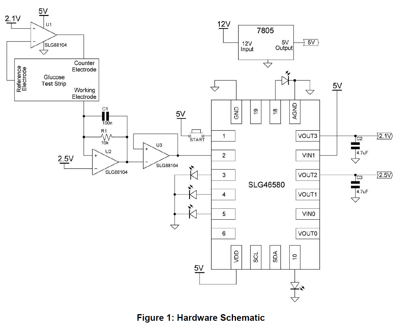
Hardware Schematic
The hardware schematic is shown in Figure 1.
The external 7805 voltage regulator is used to generate +5 V from the +12 V DC Adapter.
When a blood droplet is placed on the glucometer strip, a short circuit is created between the reference electrode and the counter electrode. This allows U1 (SLG88104V) to act as a unity gain amplifier. The output voltage is equal to the input voltage applied at the ‘+’ terminal, i.e., 2.1 V.
This short results in current flow between the counter electrode (now at 2.1 V) and the working electrode. The magnitude of the current flow is proportional to the glucose level of the blood drop.
The op-amp U2 (SLG88104V) acts as a transimpedance amplifier. The output voltage of this amplifier can be calculated with the following formula:
VOUT = [Current flow between the Counter and Working electrodes] * R1
The 100 nF capacitor C1 is used to maintain smooth voltage.
Op-amp U3 is another unity gain amplifier which maintains a constant voltage at its output. The purpose of using 2.5 V and 2.1 V in this circuit is to maintain a voltage difference of 400 mV across two of the test strip electrodes. This is necessary for the glucometer to function properly.
The output voltage of op-amp U3 is then fed to the SLG46580V’s Pin6, which is configured as an analog input/output
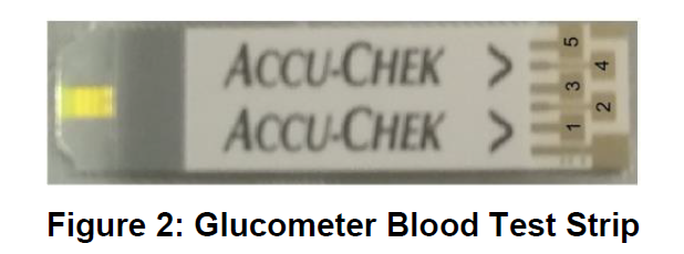
Glucometer Blood Test Strip
A typical glucometer strip is shown in Figure 2. The connections of the test strip are:
● 1 - Reference electrode
● 2 - Counter electrode
● 3 - Working electrode
● 4 and 5 - Test electrodes. These two electrodes are used to detect that the strip is inserted in the slot reserved for the strip. These two electrodes are not necessary for the functioning of the glucometer.
The connections may vary for different vendor strips; however, there should always be a reference, counter, and working electrode.
In each test strip, there is an enzyme called glucose oxidase. This enzyme reacts with the glucose in the blood sample and creates gluconic acid.
The gluconic acid then reacts with another chemical in the testing strip, called ferricyanide. The ferricyanide and the gluconic acid combine to create ferrocyanide.
Once the ferrocyanide has been created, current moves through the blood sample on the strip. The level of current allows the GreenPAK to read the level of ferrocyanide and determine how much glucose is in the sample of blood.
The output voltage from the circuit used above will range between 0 and 350 mV for typical glucose levels.
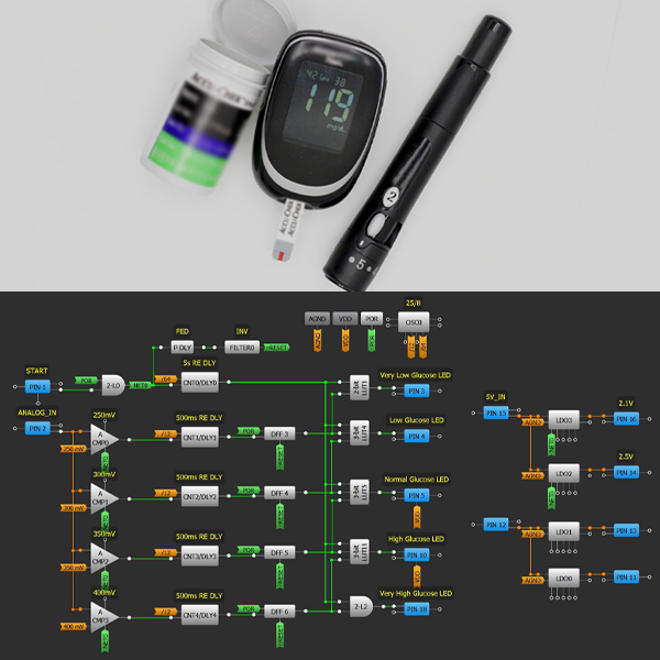
GreenPAK Design
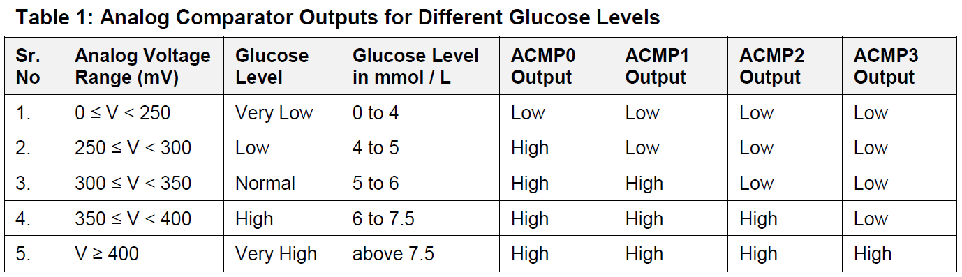
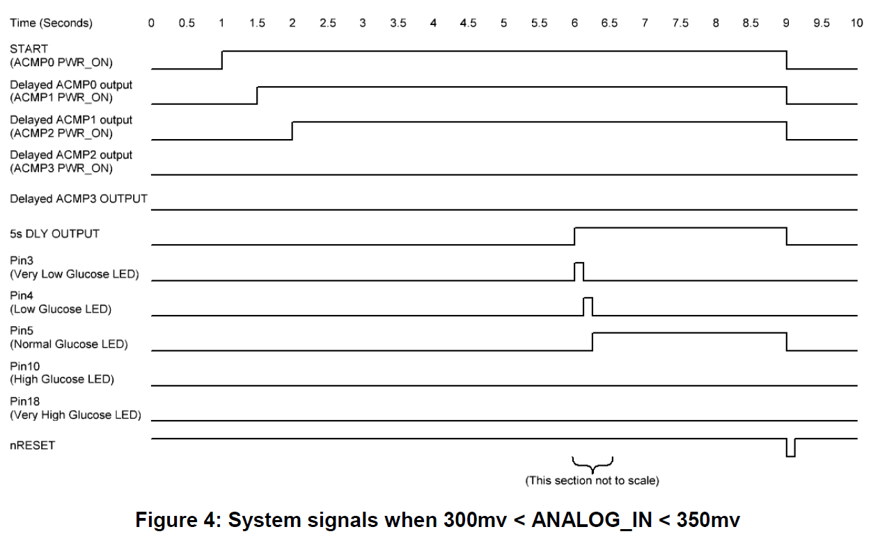
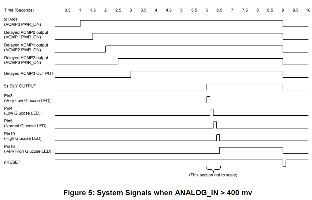
The four analog comparators (ACMPs) are used to determine the voltage of the ANALOG_IN signal received at Pin2. This design has 5 possible glucose levels, and each level corresponds to a particular voltage range. The table below gives the analog voltage ranges for each of the glucose levels.
To prevent false readings, we included several 500 ms delay blocks between the ACMPs and the rest of the circuit. These delays will help filter out any spurious signals. The sensitivity of the glucometer can be varied by varying the delay time of these delay blocks.
Since the voltage received at ANALOG_IN (Pin2) is the result of current flowing between the counter electrode and the working electrode on the test strip, the current will only last for a short period of time and may disappear quickly. In order to hold the voltages for a longer period, we used capacitor C1. However, even with the capacitor, the voltage will dissipate, causing all of the ACMPs to be LOW. To save the ANALOG_IN voltage value, we used 4 DFFs to store the analog voltage range information at the output of the 4 delay blocks.
To reduce power consumption, each ACMP is only powered on once the ANALOG_IN voltage is high enough for the next ACMP to be required. For instance, if the ANALOG_IN voltage is 325 mV and the START input goes HIGH, ACMP0 will be turned on immediately so that it can determine whether ANALOG_IN is greater than 250 mV.
Since ANALOG_IN > 250 mV, after 500 ms CNT1/DLY1 will go HIGH, which will clock DFF3 and power on ACMP1. ACMP1 will now check whether ANALOG_IN is greater than 300 mV. Again, since it is greater than 300 mV, in 500 ms the output of CNT2/DLY2 goes HIGH, which clocks DFF4 and powers on ACMP2.
At this point ANALOG_IN < 350 mV, so ACMP2 will stay LOW, meaning that DFF5 and DFF6 will both stay LOW.
Once 5 seconds has elapsed from the time that the START signal went HIGH, CNT0/DLY0 will go HIGH. This signal, as well as the DFF outputs, are connected to Look-Up Tables (LUTs), either 2-bit or 3-bit. These LUTs resolve which LED should be lit to indicate the level of glucose.
When the START signal goes LOW, a short reset pulse is triggered using the PDLY as a falling edge detector along with inverter FILTER0. This short, active-low pulse will reset the four DFFs. This will consequently power off all of the ACMPs, and ready the system to take another reading
Timing Diagrams
Comparison and Benefits
Compared to a typical glucometer, this GreenPAK-based Glucometer is smaller, less expensive, and more energy efficient. The design could easily be modified for patients with Type-1 or Type-2 diabetes.
Conclusion
In this project, Dialog GreenPAK SLG46580V and SLG88104V was used to develop a custom glucometer. The concepts used in the project could be modified to fit other medical applications. Thanks to their small size and low energy consumption, Dialog’s GreenPAK products make it possible for this design to be portable and energy efficient.