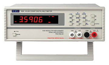
An article introducing different tests of the multimeter.
Voltage Test
First select the test type and range of a voltage, then insert the red and black test lead into the main input end and the common end for measurement。
Press [AUTO/MAN] on the test keyboard to switch between automatic range adjustment and active range adjustment. Press the up or down to increase and decrease the test range (the same for range adjustment of other tests)
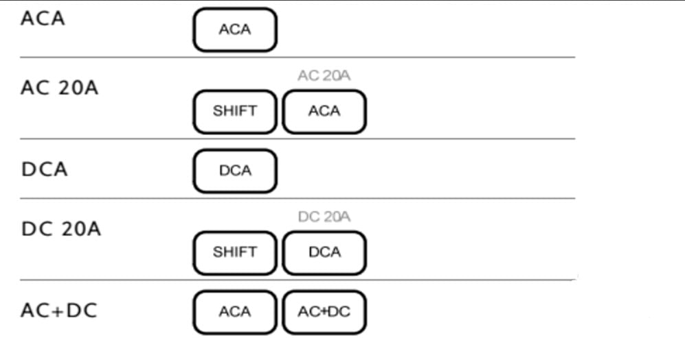
Current Test
First select a type and range for current test, then connect the red and black test leads to the current test port. The red lead is connected to the input end, and the black lead is connected to the output end. Choose the right port based on the size of the current to be tested.
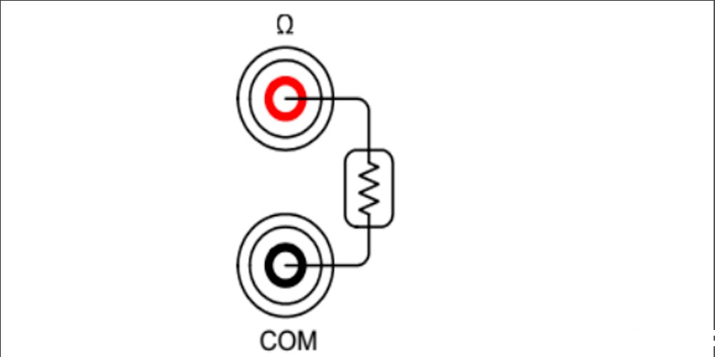
Resistance Test
Press [Ω], insert the red test lead and the black test lead into the main test port and the common terminal respectively, and then measure the resistance.
Diode Test
First press [SHIFT], then press the diode key shown in the picture. The red and black test leads are inserted into the main test port and the common port respectively to test the diode. If the display screen shows the value, the red test lead is connected to the positive pole of the diode; if not, the red test lead is connected to the negative pole.
Path Testing
First press the path testing button on the keyboard shown in the figure, then insert the red and black test lead into the main test port and the common test port respectively for measurement. When the impedance of the test is less than 5Ω, the buzzer in the multimeter will ring out. This test can verify that the impedance in the device is low enough to be considered as a path.
Capacitance Test
This test measures the total amount of electricity stored between the two poles of the capacitor. First, press the capacitance test button on the instrument panel as shown in the picture, then insert the red and black test lead into the main test port and the common test port respectively for measurement. Read the data on the display screen.
Notes:
When measuring a strong current, it is necessary to clarify whether the value of the test is within the safety test range of the multimeter.