Learn how to implement a digital ultrasonic distance sensor using the GreenPAK module
Below we described steps needed to understand how the solution has been programmed to create a digital distance measurement tool. However, if you just want to get the result of programming, download GreenPAK™ software to view the already completed GreenPAK Design File. Plug the GreenPAK Development Kit to your computer and hit the program to design the solution.
Introduction
The goal of this project is to design a digital distance sensor with the help of a GreenPAK IC. The system is designed using the ASM and other components within the GreenPAK to interact with an ultrasonic sensor.
The system is designed to control a one-shot block, which will generate the trigger pulse with the necessary width for the ultrasonic sensor and classify the returning echo signal (proportional to the distance measured) into 8 distance categories.
The interface design can be used to drive a digital distance sensor to be used in a wide variety of applications, such as parking assist systems, robotics, warning systems, etc.
Interface with Digital Ultrasonic Sensor
The system designed sends trigger pulses to the ultrasonic sensor every 100 ms. The GreenPAK internal components, together with the ASM, oversee the classification of the returning echo signal from the sensor. The ASM designed uses 8 states (states 0 to 7) to classify the echo from the ultrasonic sensor using the technique of iteratively transitioning through the states as the system waits for the echoed signal. In this way, the further the ASM goes through the states, the fewer LEDs light up.
As the system keeps measuring every 100 ms (10 times per second) it becomes easy to see the increase or decrease on the distances measured with the sensor.
Ultrasonic Distance Sensor
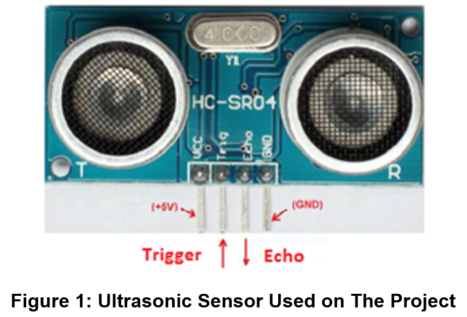
The sensor to be used in this project is the HC-SR04, which is illustrated in the following Figure 1.
The sensor uses a 5 V source on the leftmost pin and the GND connection on the rightmost pin. It has one input, which is the trigger signal, and one output, which is the echo signal. The GreenPAK generates an appropriate trigger pulse for the sensor (10 us according to the datasheet of the sensor) and measures the corresponding echo pulse signal (proportional to the distance measured) provided by the sensor.
All the logic is set within the GreenPAK using the ASM, delay blocks, counters, oscillators, D flipflops and one-shot components. The components are used to generate the required input trigger pulse for the ultrasonic sensor and classify the returning echo pulse proportional to the distance measured into distance zones as detailed in the following sections.
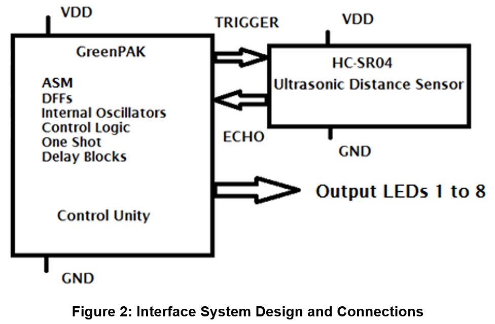
The connections needed for the project are shown in Figure 2.
The input trigger requested by the sensor is an output generated by the GreenPAK, and the echo output of the sensor is used to measure the distance by the GreenPAK. The internal signals of the system will drive a one-shot component to generate the required pulse to trigger the sensor and the returning echo will be classified, using D flip-flops, logic blocks (LUT and inverter), and a counter block, into the 8 distance zones. The D flip-flops at the end will hold the classification on the output LEDs until the next measure is done (10 measures per second).
Realization with GreenPAK Designer
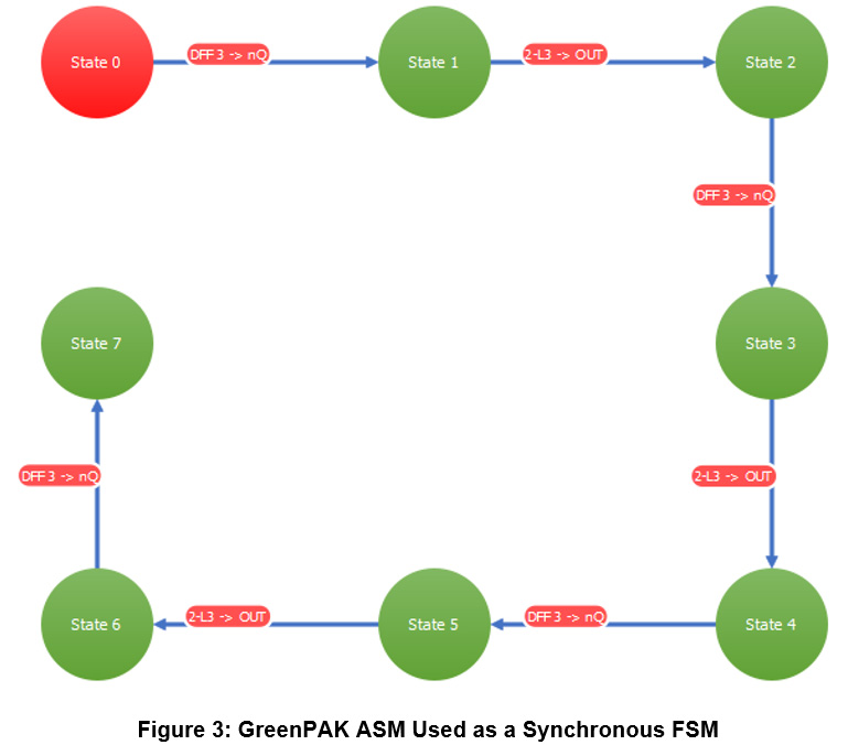
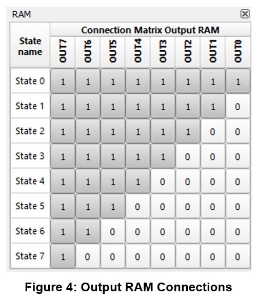
This design will demonstrate the state machine functionality of the GreenPAK. Since there are eight states within the proposed state machine, the GreenPAK SLG46537 is appropriate for the project. The machine was designed on the GreenPAK Designer software as shown in Figure 3, and the outputs definitions are set on the RAM diagram of Figure 4.
The full diagram of the circuit designed for the project can be seen in Figure 5. The blocks and their functionalities are described after the Figure 5.
As can be seen in Figure 3, Figure 4 and Figure 5, the system is designed to work in sequential-state order to generate a 10 us trigger pulse for the ultrasonic distance sensor, using CNT2/DLY2 block as a one-shot component together with the 25 MHz clock from OSC1 CLK, to generate the signal on PIN4 TRIG_OUT output. This one-shot component is triggered by the CNT4/DLY4 counter block (OSC0 CLK/12 = 2kHz clock) every 100 ms, triggering the sensor 10 times per second. The echo signal, whose latency is proportional to the distance measured, comes from the PIN2 ECHO input. The set of components DFF4 and DFF4, CNT3/DLY3, LUT9 create the lag to follow through the states of the ASM. As can be seen in Figure 3 and Figure 4, the further the system traverses through the states, the fewer outputs are triggered.
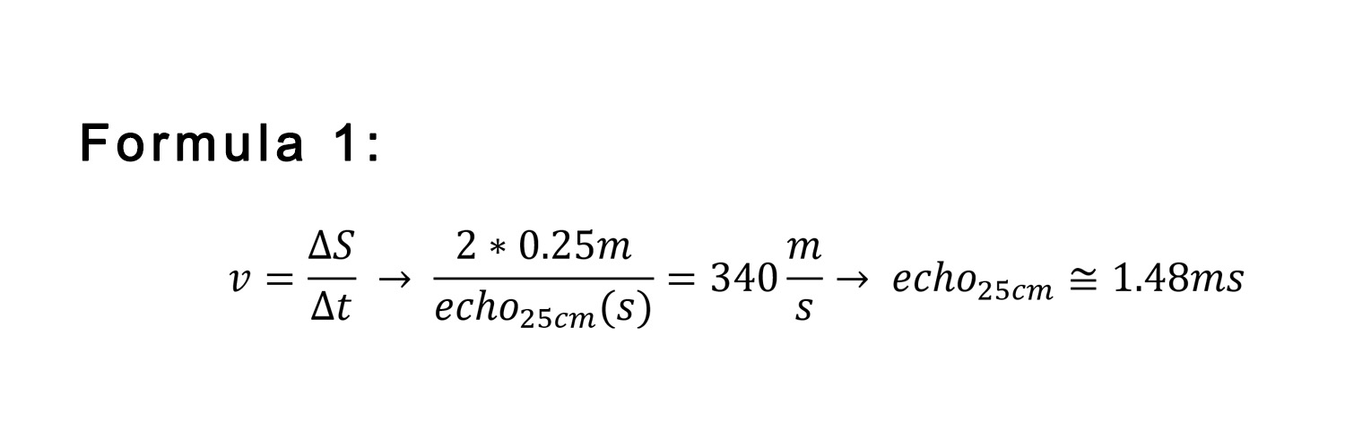
The steps of the distance zones are 1.48 ms (echo signal), which is proportional to 0.25 cm increments, as shown in the following equation. That way we have 8 distance zones, from 0 to 2 m in 25 cm steps, as shown in Table 1.
Results
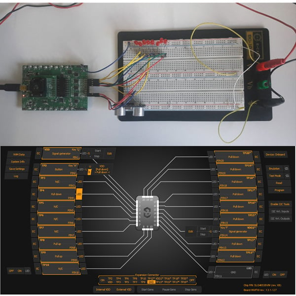
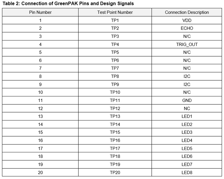
To test the design, the configuration used on the emulation tool provided by the software can be seen in Figure 6. The connections on the pins of the emulation software can be seen after it on Table 2.
The emulation tests show that the design works as expected by providing an interface system to interact with the ultrasonic sensor. The emulation tool provided by GreenPAK proved itself a great simulation tool to test the design logic without programming the chip and a good environment to integrate the development process.
The circuit tests were made using an external 5 V source (also designed and developed by the author) in order to provide the nominal sensor voltage. Figure 7 shows the external source used (020 V external source).
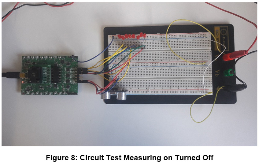
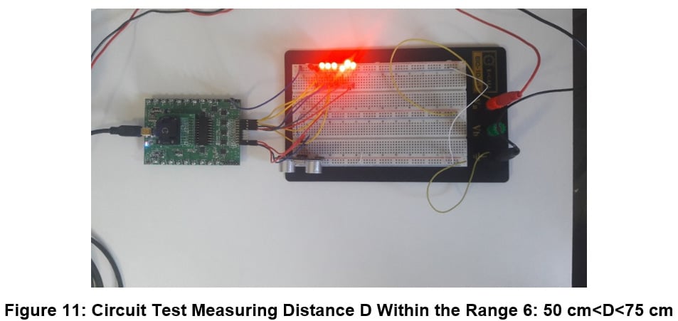
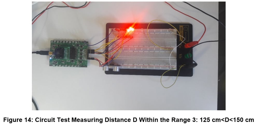
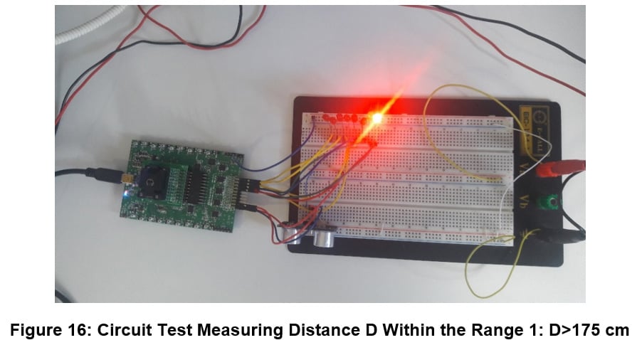
To test the circuit, the echo output from the sensor was connected on the input of PIN2 and the trigger input was connected on PIN4. With that connection, we could test the circuit for each one of the ranges of distance specified on Table 1 and the results were as follows in Figure 8, Figure 9, Figure 10, Figure 11, Figure 12, Figure 13, Figure 14, Figure 15 and Figure 16.
The results prove that the circuit works as expected, and the GreenPAK module is capable of acting as the interface for the ultrasonic distance sensor. From the tests, the circuit designed could use the state machine and the internal components to generate the required trigger pulse and classify the returning echo lag into the categories specified (with 25 cm steps). These measurements were made with the system online, measuring every 100 ms (10 times per second), showing that the circuit works well for continuous distance measuring applications, such as car parking assisting devices and so on.
Possible Additions
To implement further improvements on the project, the designer could increase the distance to encapsulate the entire ultrasonic sensor range (we are currently capable of classifying half of the range from 0 m to 2 m, and the complete range is from 0 m to 4 m). Another possible improvement would be to convert the distance measured echo pulse to be displayed in BCD displays or LCD displays.
Conclusion
In this project, a digital ultrasonic distance sensor was implemented using the GreenPAK module as a control unit to drive the sensor and interpret its echo pulse output. The GreenPAK implements an ASM along with several other internal components to drive the system.
The GreenPAK development software and development board proved to be excellent tools for fast prototyping and simulation during the development process. The GreenPAK’s internal resources, including the ASM, oscillators, logic, and GPIOs were easy to configure to implement the desired functionality for this design.