Find out how to create a Class-D Audio Amplifier using GreenPAK™
SLG46140V.
Below we described steps needed to understand how the solution has been programmed to create the audio amplifier. However, if you just want to get the result of programming, download GreenPAK™ Designer software to view the already completed GreenPAK Design File. Plug the GreenPAK Development Kit to your computer and hit the program to design the device.
In this project, we will use a Dialog GreenPAK SLG46140V to create a Class-D Audio Amplifier. A Class-D amplifier takes an analog audio signal, converts it into a digital PWM signal, and then filters the PWM signal to recapture the analog signal with a greater amplitude for greater volume.
Input and Output Signals
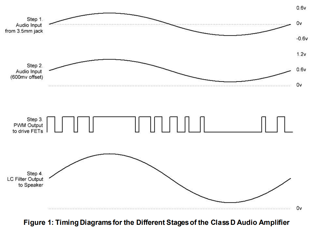
Figure 1 shows the input and output signals used in this project. The analog waves that come out of an iPhone headphone jack are centered around 0 v and have an amplitude of between 1-2 v. We need to process that analog signal through our GreenPAK’s ADC (analog to digital converter), but the GreenPAK ADC can only convert positive values from 50 mv to 1200 mv. This means that the first thing we need to do is add a 600 mv DC offset to the input signal. The amplitude of the input signal remains the same, but it is now centered around 600 mv as shown in Step 2 of Figure 1.
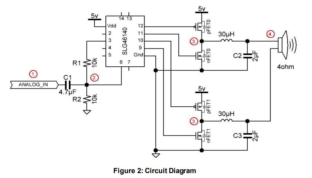
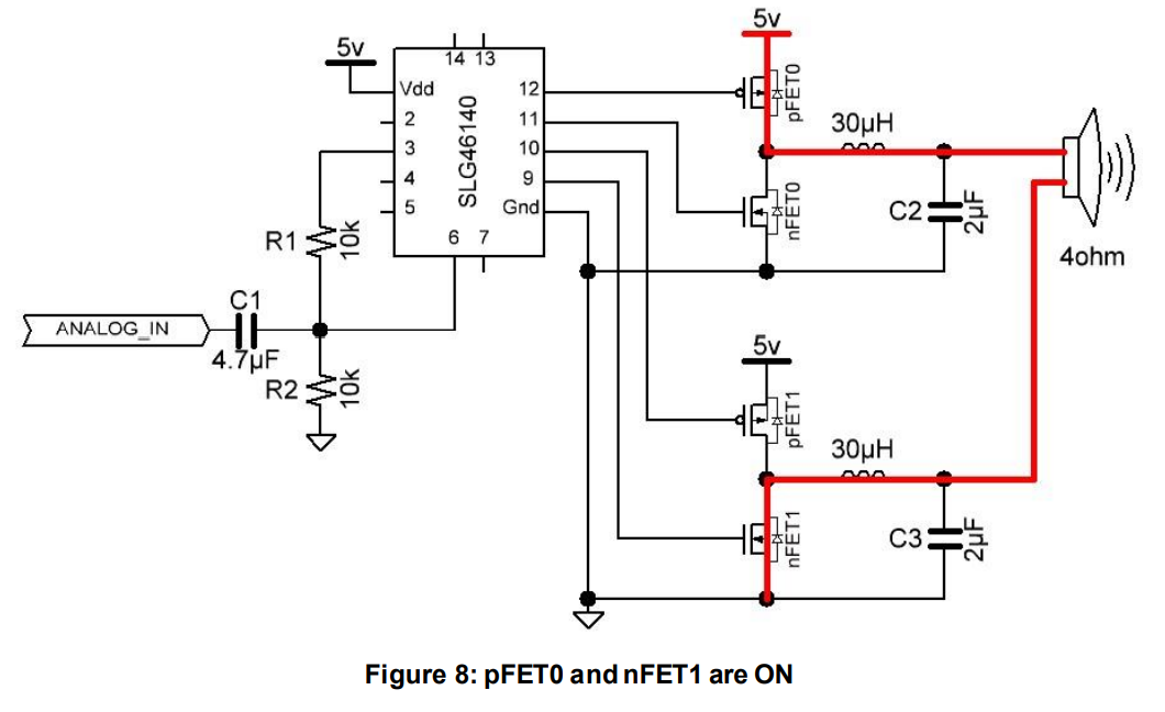
We can do that by adding a series capacitor and a resistive divider to our circuit, as shown in Step 2 of Figure 2. The voltage coming out of the GreenPAK’s Pin3 is 1.2 v, which means that the waveform that enters Pin6 will be centered around 0.6 v. We’ll discuss how to create that 1.2 v rail in the GreenPAK Design section.
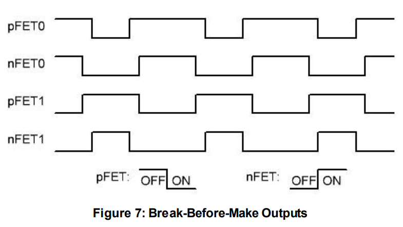
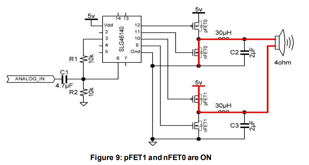
The GreenPAK takes the voltage that it receives at Pin6 and converts it into several different PWM signals which are output on Pins 9-12. Those signals are used to control the gates of 4 MOSFETs which are configured as an H-Bridge. In order to maximize the voltage potential across the speaker, pFET0 and nFET1 are turned on at the same time, and pFET1 and nFET0 are turned on at the same time.
To recreate our analog input signal, we added a pair of LC filters to both sides of the H-Bridge. The outputs of both filters are connected to the speaker terminals.
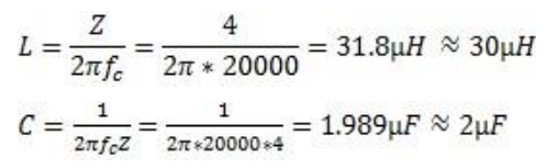
We desired a cutoff frequency of 20kHz, since that is the upper range of human hearing. We measured the speaker impedance at 4Ω, and used those values to calculate the capacitance and inductance needed for our LC filters.
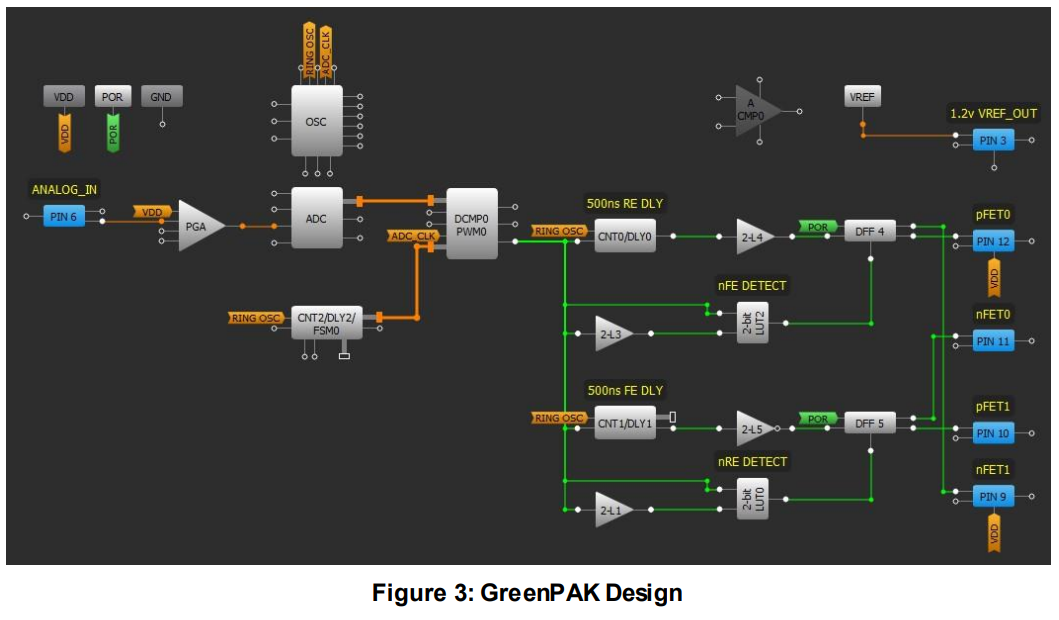
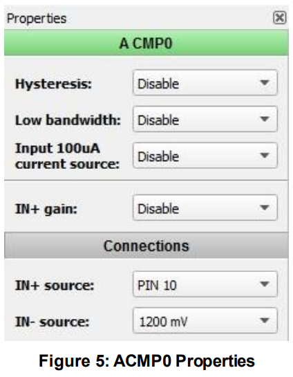
The first thing we needed to do in the GreenPAK design was to create a 1.2 v rail to help add the 600 mV offset to our input signal. We accomplished this by configuring the VREF block so that it outputs the ACMP0 threshold to Pin3. We set ACMP0’s threshold to 1200 mV as shown in Figure 5.
Pin6 receives the analog input signal with the 600 mV offset. The signal is passed through the PGA with a gain of x1, and then is converted into an 8-bit value by the ADC. Meanwhile, CNT2/DLY2 is configured as an 8-bit ripple counter and its clock line is connected to the GreenPAK’s 25 MHz RING oscillator. CNT2’s count value starts at 255, and every time it is clocked the count value is decremented. When CNT2 has counted 255 clocks, it rolls over to 255 and continues to count down. The DCMP0/PWM0 block is used to generate a PWM output so that when the ADC value is greater than the CNT2 value, the DCP0/PWM0 block outputs HIGH, as shown in Figure 6. This means that when the Analog voltage at Pin6 is higher, the ADC will output a bigger 8-bit number, and the DCMP’s output pulse length will be longer.
The output of the DCMP0/PWM0 block is sent through some break-before-make circuitry to ensure that our external H-bridge works properly. We want to make sure that pFET0 and nFET0 are never turned on at the same time, which would short our power supply to ground. Likewise, we never want pFET1 and nFET1 to be turned on at the same time.
We used delay blocks, DFFs, and edge detectors to create the break-before-make circuitry. When the output of DCMP0 goes HIGH, the rising edge detector composed of 2-bit LUT1 and 2-bit LUT0 is used to reset DFF5, which turns off both nFET0 and pFET1. 500 ns later, DLY0 clocks POR through DFF4, which will turn on nFET1 and pFET0. The same timing occurs in the inverse when there is a falling edge on the output of DCMP0.
When opposite sides of the H-Bridge are ON at the same time, the full power supply voltage can be delivered to the speaker.
The LC filters smooth out the outputs to create a less choppy signal, thus recreating the original audio waveform.
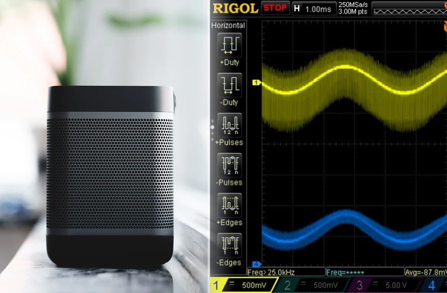
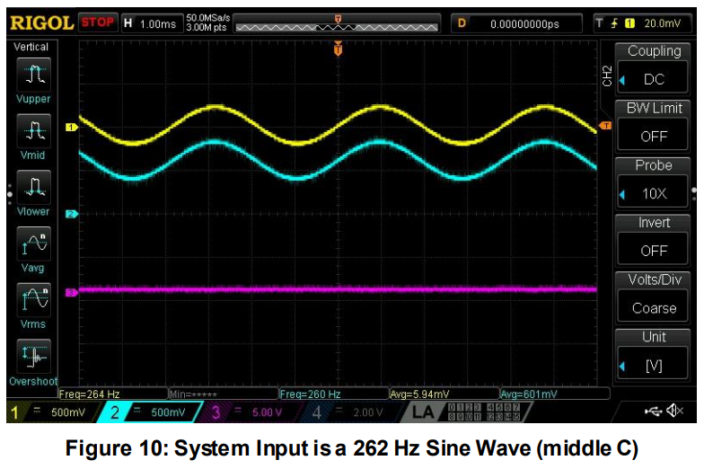
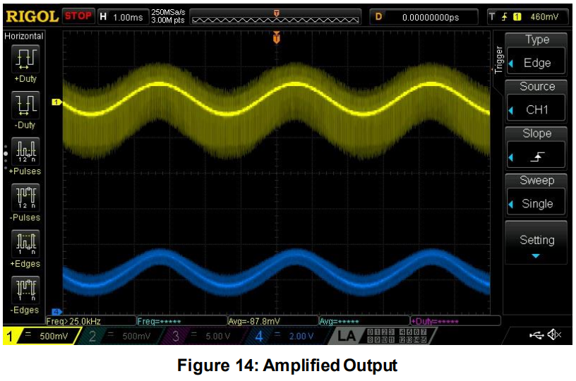
In the following oscilloscope waveforms, the channels were connected to the following signals:
Channel 1 (yellow) – Output from 3.5 mm audio jack
Channel 2 (blue) – Pin6 (ANALOG_IN)
Channel 3 (pink) – Pin9 (nFET1)
Channel 4 (dark blue) – Output of top LC filter
We tested our circuit with a 262 Hz sinewave, which corresponds to the note “Middle C.” As you can see in Figure 10, the ANALOG_IN signal has a 600 mV DC offset from the audio jack output. In Figure 10, we disconnected the GreenPAK’s Pins 9-12 to reduce switching noise.
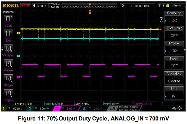
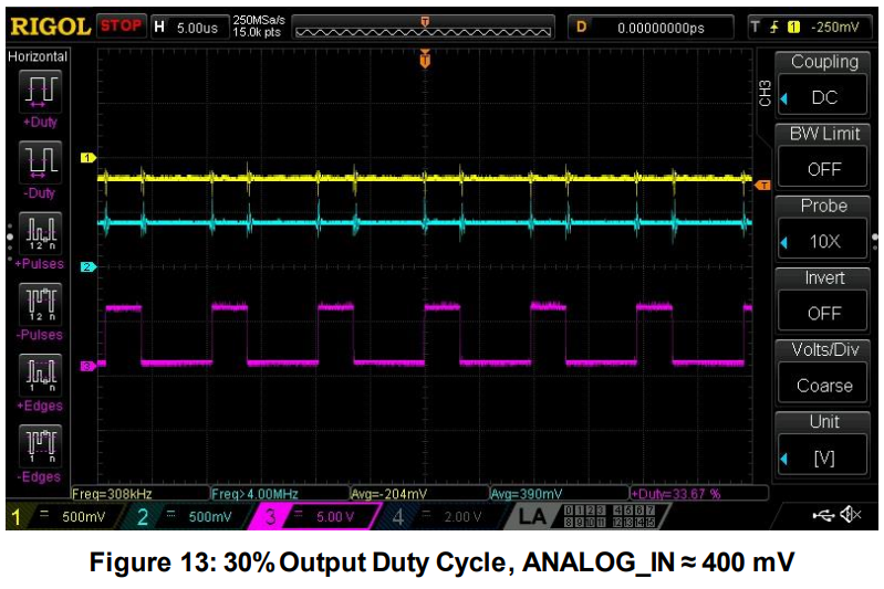
If we enable Pins 9-12 and zoom in, we can see the duty cycle of Pin9 change at different points in the sinewave. We also encounter some switching noise. This is shown in Figure 11, Figure 12, and Figure 13.
In Figure 14, when we zoom back out you can see that the input waveform has been amplified by our circuit and the output is the same frequency as the input. To hear the amplifier in action, watch the video connected to this project.
Conclusion
In this project, we created a Class-D amplifier with a Dialog GreenPAK SLG46140V and a few passive external components. We created a DC offset to prepare the input signal to be processed by the GreenPAK’s ADC and used an H-Bridge with a pair of LC filters on the output to recreate the input signal.
Since this design only uses about half of the digital logic resources inside the SLG46140V, a designer could use the rest of the logic blocks to add more functionality to the design.