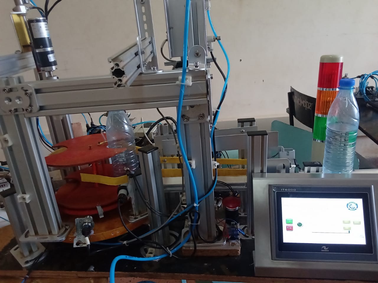
This article presents a novel project aimed at addressing the challenges posed by manual production line processes by implementing an automated filling and capping system in a compact DIY design.
Features of the Prototype
The Main Features of the project include the following;
- Non-contact control panel consisting of Capacitive sensors
- Accurately rotating turn table.
- High torque conveyor belt system.
- High precision in Sensor detection and inspection.
- Easy program loading and debugging.
- 24V mini fluid pump.
- DCV valve.
- Double-acting cylinder.
- Conveyor Belt.
- Programmable Logic Control (PLC) Unit.
- Mechanical structure.
- Human Machine Interface (HMI)
- RS232 Cable
Step-by-step Operations
The following is a step-by-step operation of the project;
- Turn on the mains power using a circuit breaker, this will turn on the PSU.
- There is an E-stop button that has to be pressed.
- Two push buttons act as the start and stop switches. To start the system's operation, touch on the HMI panel (Start).
- When the object (bottle) is placed on the conveyor, and the optical sensor at the start point is triggered, the conveyor moves it to the filling station where there is a sensor to stop the conveyor for the filling process.
- The conveyor stops for the filling station and then fills for some time after which it stops.
- The conveyor moves the filled bottle to a turn table where capping and inspection are done on the already-filled bottle.
- After some specific turns on the turn table are made and the inspection process is done, the table turns to eject the perfect bottle. If the bottle has errors like having no cap, the turn table can be stopped to resolve the problem.
CAD Designs of the DIY Project
The design of this System was done using Autodesk Inventor Software for high accuracy and
precision in parts.
The System design consists of;
- An entry conveyor moves the bottle toward the turn table.
- A turn table to rotate the object for the resultant processes.
- A filling unit.
- Cap holder.
- Cap Screwing Unit.
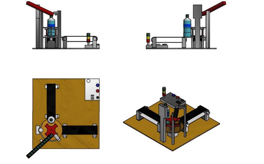
Below are orthographic views of the system;
CAD assembly of the whole project. Image used courtesy of Bob Odhiambo.
CAD assembly of the rotary platform. Image used courtesy of Bob Odhiambo.
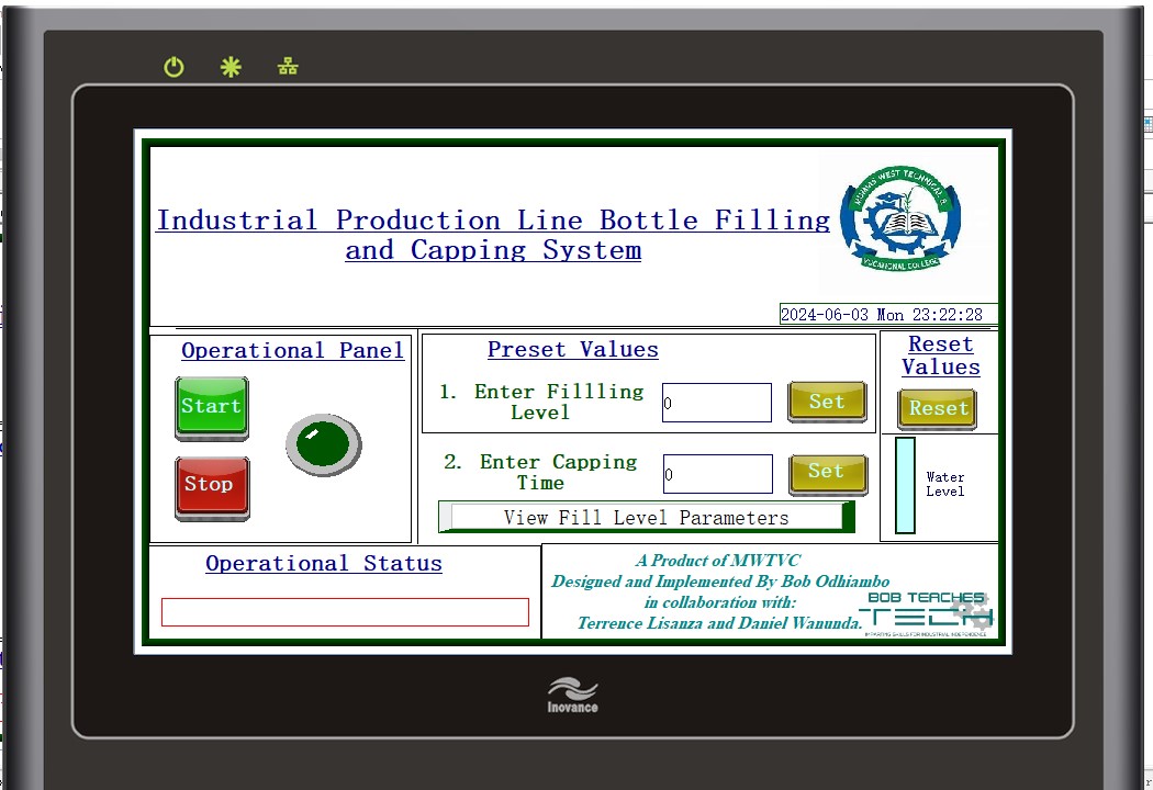
HMI Design Implementation
The INOTOUCH Editor was used to design the INOVANCE IT6000 HMI Screen for a more
interactive machine. The design has 2 pages, the main screen and the fill parameter screen. In the
front page, filling and capping time can be set, and also is where the machine’s operations can be
started or stopped. The second page has a fill parameter range (Full, Half, and Low), to aid in
keying in the right timer range based on your filling needs.
The interactive human-machine interface that is used to change the fill parameters. Image used courtesy of Bob Odhiambo.
Software Implementation
In the software implementation, we utilize the GX works software to write PLC and Ladder logic
Programs to automate the system. The written ladder program is loaded to the PLC using an
RS286 interface cable.
The PLC program is attached in the resource section.
Video Showing The System In Action