A step-by-step guide to making a USB-powered fire alarm that senses flames and sounds an alert.
With just a few basic electronic components, you can build your own flame detector that sounds an alarm automatically — no programming, no development board required. Simple, practical, and perfect for electronics beginners!
Working Principle
This flame alarm detects the infrared light released by the flame through an infrared flame sensor module. When the module detects a signal, it outputs a low level that triggers the PNP transistor to conduct, allowing the buzzer to sound an alarm.
Wiring Diagram
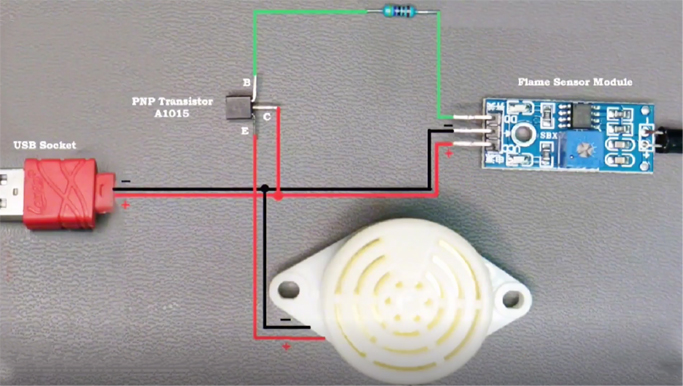
Wiring diagram showing how to connect the flame sensor, buzzer, PNP transistor, and USB power.
Required Components
Soldering Procedure
Step 1: Identify Transistor Pins
We use PNP transistors (e.g. A1015 or S8550).
With the flat (labeled) side facing you, the pins in order from left to right are:
E (emitter), C (collector) ,B (base)
Step 2: Connect the Buzzer to the Transistor
Solder the positive terminal of the buzzer to the Emitter (E) of the transistor.
Solder the negative terminal of the buzzer to the GND (black wire) of the USB cable.
Step 3: Connect the Collector of the Transistor to the Power Supply
Solder the wire from the Collector (C) of the transistor to the +5V (red wire) of the USB cable.
Also connect the same +5V wire to the VCC pin of the flame sensor module.
Step 4: Connect the Ground Wire
Connect the GND (black) wire from the USB to the GND pin of the flame sensor module.
This allows all components to share a common ground reference.
Step 5: Connect the Control Signal
Solder a 4.7kΩ current-limiting resistor to the Base (B) of the transistor.
Connect the other end of the resistor to the DO (digital output) pin on the flame sensor module.
Step 6: Isolate and Secure
Insulate all exposed solder joints with heat shrink tubing or electrical tape.
Before energizing, double check all connections for shorts or cold solder joints.
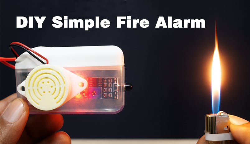
Assembly and flame response test of the DIY fire alarm.
Testing and Adjustment
Power the circuit via any 5V USB adapter (e.g. cell phone charger). The buzzer should sound when a flame (e.g. from a lighter) is near the sensor.
Adjust the sensitivity:
Turn the blue potentiometer on the sensor module clockwise or counterclockwise.
Enjoyed the project? Give it a try and make your own!