This project guides on how to accomplish Electric Scooter Controller. It describes the implemented logic, the HVPAK SLG47115’s application and the obtained results of a typical scooter controller.
Implementation and Configuration of Electric Scooter Controller
The implementation of the Electric Scooter Controller is based on the HVPAK SLG47115V. This CMIC contains internal Analog Comparators, PWM controllers, and High-Voltage Integrated H-Bridge/dual Half-Bridge functionality that can be used as a pre-driver for the DC motor with internal speed regulation, based on the user selection and throttle position.
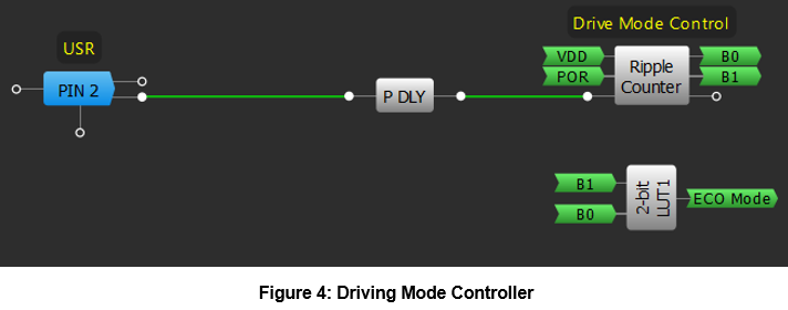
The driving mode configuration, which determines the maximum allowed speed for the DC motor, is implemented with the internal ripple counter and the programmable delay/edge detector, as it is shown in Figure 4 in the Go Configure Software Hub. The complete design file can be found here.
As an electric vehicle, the electric scooter is a battery-powered vehicle designed for convenient and eco-friendly personal transportation. Classified as a form of micro mobility, they are designed with a large center platform on which the rider stands.
It is generally based on an electric motor normally placed on the front wheel that is electronically controlled by a central device located on the user’s front control panel. The brake system includes disc brakes on the rear wheel and the electric motor lock can also be used as an additional brake.
A typical scooter diagram is shown in Figure 1, where the main components are indicated.
The entire scooter control is implemented in the front panel, where power button is located, the measured speed is shown, the drive modes can be selected and some other options like turning on the headlight can be selected.
Electric scooters are usually designed to have three different driving modes with a trade-off between battery life and maximum speed. These modes are user selectable on the front panel.
The Eco drive mode is defined as the lowest speed mode. It usually reaches 10–15 km/h depending on the scooter model and is designed for energy saving and beginners.
The standard mode, or Drive, has a top speed of 15–20 km/h and it is the recommended mode for driving in urban environments.
The Sport mode is the fastest. The top speed is limited to the maximum of the scooter (20–25 km/h typically) and is the least efficient mode in terms of battery life.
All these modes are selected by pressing the button located on the front panel on the handlebars by the driver.
In the same place, the throttle and brake lever are placed. The throttle is based on a potentiometer, so its voltage output is proportional to the user’s desired speed. The brake lever moves the disc brake and, also, electronically activates the brake light located at the rear of the scooter.
Scooter Controller Design Diagram And Schematic
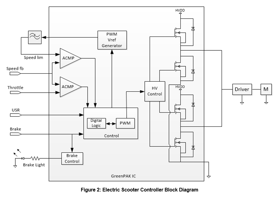
The Electric Scooter Controller described and implemented in this article is based on the block diagram shown in Figure 2.
A DC motor is the main actuator to be controlled. To do this, the internal HV GPIOs of the SLG47115 are configured as a double half — bridge to work as a pre-driver for external FET’s that drive the motor. These pins, as the motor output controllers, define whether the motor moves forward, brake or is at coast mode.
The pins are managed with the internal HV Out control module of the HVPAK IC, which is controlled by the implemented internal logic based on the speed sensor output (the speed feedback) and the throttle position. This control also uses a PWM, generated with one of the internals PWM modules of the HVPAK IC, and the analog comparators connected to the actual speed, throttle position and speed limit signals. The varying duty cycle of the PWM is used to regulate the motor speed.
To set the maximum speed determined by the driving mode selected by the user, the second PWM module is applied. A PWM signal with different duty cycle is generated by means of the user selection, and it is then filtered with an external low-pass filter, thus obtaining a voltage reference signal related to the maximum speed that is used for the speed regulation.
All the scooter motion, including the internal logic and the PWM regulation, depends on the brake input signal. When it is enabled, the entire motion logic is disabled by the brake control and the corresponding light indicator is enabled.
The driving mode is selected by the user, with an external button and the corresponding deglitch filter generating edges that allow the system to switch between the different options.
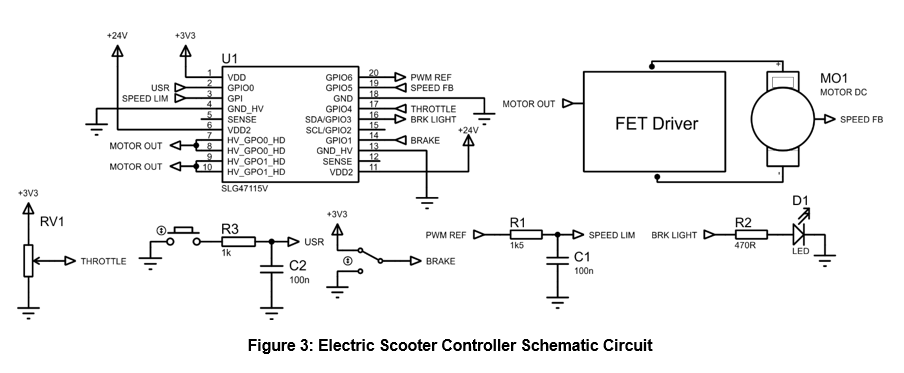
The diagram shown in Figure 2 is represented, considering the required external components, in the schematic circuit shown in Figure 3.
Implementation and Configuration of Electric Scooter Controller
The implementation of the Electric Scooter Controller is based on the HVPAK SLG47115V. This CMIC contains internal Analog Comparators, PWM controllers, and High-Voltage Integrated H-Bridge/dual Half-Bridge functionality that can be used as a pre-driver for the DC motor with internal speed regulation, based on the user selection and throttle position.
The driving mode configuration, which determines the maximum allowed speed for the DC motor, is implemented with the internal ripple counter and the programmable delay/edge detector, as it is shown in Figure 4 in the Go Configure Software Hub. The complete design file can be found here.
When a falling edge is detected by the P DLY module, the ripple counter increments its output, which is configured to vary between 0 and 2 (corresponding to ECO, Drive, and Sport modes respectively). The ECO mode is particularly detected with the 2-bit LUT1 output, which is used for speed control as it is described later.
The configuration of the ripple counter is shown in Figure 5.

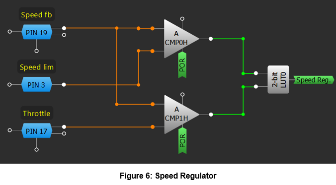
The speed regulation stage of the controller is implemented by using the internal logic and analog comparators with external reference, as in Figure 6.
The throttle (an external potentiometer) and the speed limit signal are connected to analog comparators ACMP0H and ACMP1H and compared with the speed sensor output connected to PIN 19. The ACMP0H monitors the actual speed versus the speed limit (established by the user selected driving mode) while the ACMP1H controls the actual speed versus the throttle position. Both comparisons, with the corresponding logic implemented with 2-bit LUT0, determine if the DC motor speed must be increased or decreased.
2-bit LUT0 is configured to increment the DC motor speed when it is necessary only. That is, the speed will go high if the current speed (obtained from the sensor output) is lower than the required by the throttle position and if it is lower than the speed limit. If actual speed is higher than the throttle position, or it is over the speed limit, the 2-bit LUT0 output will be low, to reduce the motor speed.
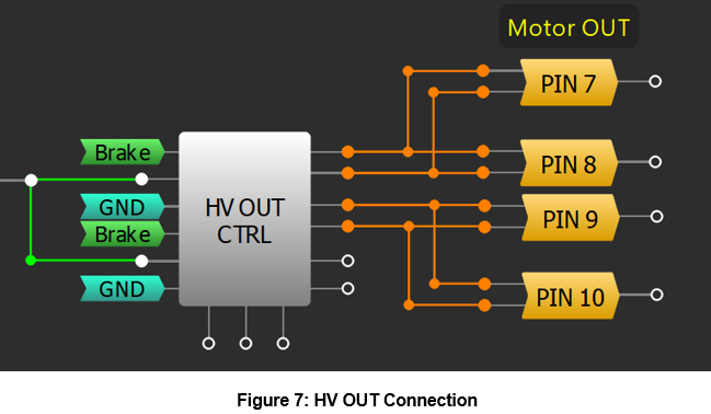
As mentioned in previous sections, the DC motor control signals are generated and regulated by a PWM connected to the HV GPIOs of the HVPAK configured as half bridge. This configuration is required to obtain the desired voltage with a high current output which is to be used as the pre-driver signal for the motor FET based driver. To obtain higher current drive capability, both half bridge legs are used in parallel.
Also, as the HV GPIO outputs are not used for direct motor driving, the slew rate of HV OUT Control module is configured in fast mode. The HV GPIO ports connections, and its configuration, are shown in Figure 7 and Figure 8.

To generate the PWM signal for speed regulation, PWM0 module is used. PWM is configured to have the higher frequency, 98.04 KHz, that can be generated with the high frequency internal oscillator (25 MHz internal oscillator). The duty cycle control is configured as a duty cycle counter, which can be incremented or decremented with an external control signal. This control signal is obtained from the speed regulator. When 2-bit LUT0 output is high, the speed must be incremented so the duty cycle goes high. In the other way, when 2-bit LUT0 is low, the speed must be decremented so the duty cycle goes low. The PWM is connected to the HV OUT module to control the half bridge output.
The configuration of PWM0 module can be seen in Figure 9.

As shown previously, speed control is implemented with analog comparators ACMP1H sensing the actual speed and the throttle position, the ACMP0H connected to the speed feedback and an external reference voltage related to the speed limit. To generate the reference, the PWM1 module output signal is used, filtered with an external first order RC low pass filter. PWM 1 module is configured to generate a 98.04 KHz PWM output signal with a configurable duty cycle from the internal register file. Each time the controller changes the driving mode, the PWM receives a control pulse to change the register pointer, so the corresponding speed limit (that is, the corresponding voltage reference) is generated. These changes are made by generating a pulse in the Duty Cycle Clock Signal (when the mode changes from ECO to Drive or from Drive to Sport) or in the PWR Down signal (when Sport to ECO mode). Those pulses are triggered by an edge in the bit 0 output of the Drive Mode Control Ripple Counter or by detecting the ECO mode with the corresponding filter, respectively.
PWM output is then connected to PIN 20 and filtered externally with the RC low pass filter. The output of the filter is connected, as the reference speed, to PIN 3, the ACMP0H negative input voltage.
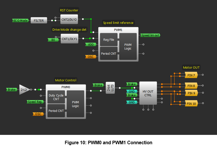
The connection of both PWM0 and PWM1, and the configuration of PWM1 module are shown in Figure 10 and Figure 11.

The entire motor control also depends on the brake lever signal. When low, this signal stops the PWM0 module (corresponding to the motor control), disables the HV OUT control and enables the Brake Light blinking with the OSC0 output 1 (with a frequency of 4 Hz), configured as shown in Figure 12.

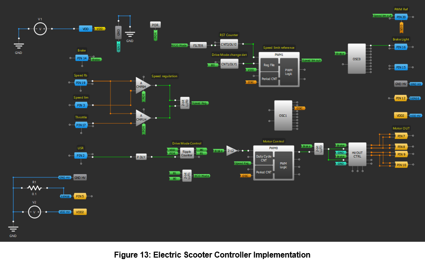
The entire Electric Scooter controller implementation diagram is shown in Figure 13.
Testing Results
To test the implementation, the entire system was simulated with the Go Configure Software Hub Simulator, performing several transient analyses to verify the behavior of different parts of the design. It is important to consider that all the dynamics of the external signal were time scaled to be simulated with an acceptable execution time. This fact implies that the external signals, such as throttle output and speed feedback where much faster than the real ones, but without losing any condition about the system behavior.
To verify the speed regulation, simulated signals were injected to the corresponding pins with the custom signal generators to make the system vary the PWM duty cycle in the corresponding way. A constant speed limit signal and speed feedback signal were used, while the throttle speed set was varied between values lower than the current speed and higher than the current speed.
With the described conditions, it was expected that the PWM0 duty cycle would first go down and then rise, based on the speed measurements. In Figure 14, the simulation results can be seen, showing the expected behavior.
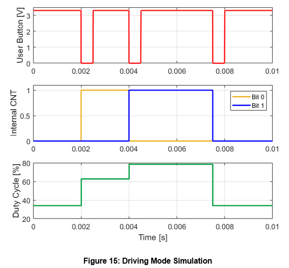
As the speed regulator was verified and validated, the user driving mode selector was tested. A simulated user button signal was injected to the corresponding pin, and the internal ripple counter and PWM1 duty cycle were measured. Each time a falling edge was detected, it was expected that the internal counter and the PWM1 duty changes, generating a voltage reference related to the corresponding driving mode. In Figure 15, all the input and output signals of the simulation are shown, resulting in positive results.
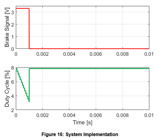
Finally, the brake response was simulated. In this case, if the brake signal was present, the PWM0 should stop regulating (and the HV GPIO pins should be disabled). The input signal and the PWM0 duty cycle can be seen in Figure 16, showing successful results.
Conclusion
In this article we explained how to implement an Electric Scooter Controller that can be applied for both new devices and repair used ones. Electric and sustainable mobility applications are nowadays one of the main developments and markets, so such type of controllers is highly required.
There are several methods of implementing these controllers, using different type of technologies. In this application note, the HVPAK SLG47115V is used as the main device, due to the high-voltage control capability and the analog and digital resources that are available. The implementation shows how different analog features of the IC can be applied and, also, how DC motors can be controlled using the IC as the pre-driver.
The size of the entire control system is smaller than many other implementations and outlines where HVPAK can be used and replace other commercial devices.