This project describes how to control a servo motor using a flex sensor, GreenPAK and
OpAmp.
Below we described steps needed to understand how the solution has been programmed to create the flex sensor-controlled servo motor. However, if you just want to get the result of programming, download GreenPAK™ Designer software to view the already completed GreenPAK Design File. Plug the GreenPAK Development Kit to your computer and hit the program to design the device.
The design uses a GreenPAK to control the duty cycle signal for a servo motor, and a Micropower Operational Amplifier to provide and adjust the signal from the flex sensor to the GreenPAK.
Construction and Operating Principle
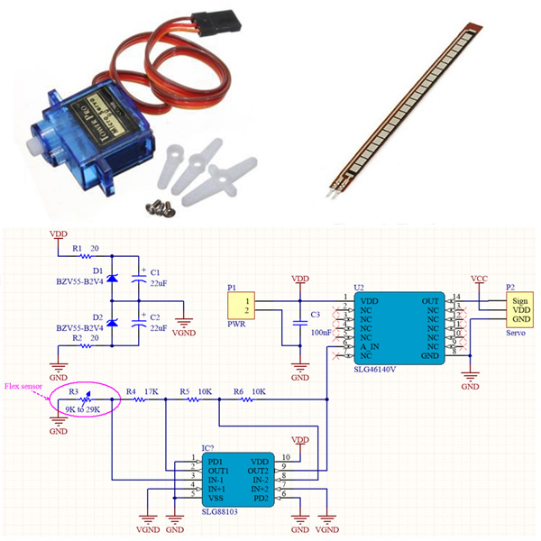
This design consists of a flexible sensor, dual CMOS Op-Amp, GreenPAK IC, and a servo motor. The connection diagram is shown in Figure 1.
The flex sensor used in this design is the SparkFun SEN-08606. An image is shown in Figure 2. This flex sensor is a variable resistor. The flex sensor is a sensor that changes its resistance depending on the amount the sensor is bent. The flex sensor converts the amount of bend to electrical resistance - the more the bend, the higher the resistance value. Sensors like these were used in the Nintendo Power Glove.
The Dual CMOS OpAmp is used as a signal amplifier and to adjust the voltage at the GreenPAK analog input (ADC input detection range is from 30 mV to 1030 mV). The OpAmps are supplied by a single voltage source, therefore, in the design, we used a part of the scheme where a virtual ground is implemented. The scheme of the OpAmp external circuitry connection is typical of inverting amplifiers with dual voltage supply OpAmps. The formula for calculating the output voltage is shown in Formula 1.
The GreenPAK operates as an analog voltage converter into a PWM signal with the necessary parameters for controlling a servo motor.
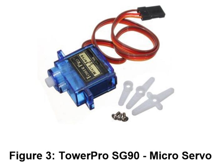
The servo motor used in this design is the TowerPro SG90 - Micro Servo, as shown in Figure 3. One can substitute other servo motors having the same control type.
This servo can rotate approximately 180 degrees (90 in each direction) and works just like a standard radio control (RC) model servo. Typical with RC servos, the position is determined by the PWM duty cycle. The center position "0" corresponds with ~1.5 ms pulse width. The right most position "90" – ~2.5 ms, and the most left position "-90" – ~0.5 ms.
The design implementation with the GreenPAK is shown in Figure 4.
The design is based on three parts:
1. Input voltage to time width converter;
2. 50 Hz generator;
3. Pulse width shaper.
The first part was implemented using PGA, ADC, and CNT3/DLY3/FSM1 blocks. The PGA block is configured with default settings, so the PGA output will equal the input signal on PIN6 (A_IN). The ADC block is configured with default settings as well (see Figure 5).
The ADC block converts input voltage within the range of 30 mV to 1030 mV into an 8-bit digital code (min value is 0 for 30 mV and max value is 255 for 1030 mV). The CNT3/DLY3/FSM1 block is configured as a delay that takes counter data from the ADC. This ensures voltage to time delay conversion.
The second part was implemented using 2-bit LUT0 and CNT0/DLY0 blocks. LUT0 was configured as an inverter. The CNT0/DLY0 block is configured as a delay for 19.98 ms (~50 Hz). The combination of these blocks implements a signal generator where its period equals the delay time.
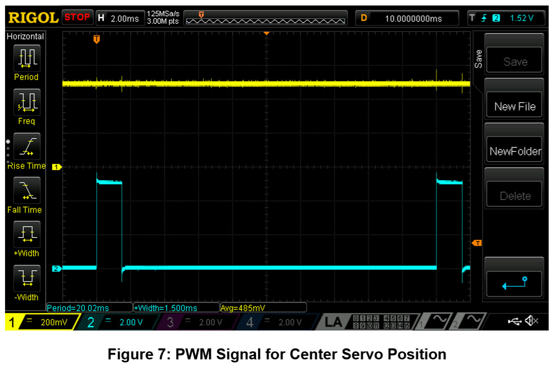
The third part was implemented with CNT1/DLY1, OSC, CNT2/DLY2/FSM0, and CNT3/DLY3/FSM1 blocks. The CNT1/DLY1 block generates a constant pulse having a width of 0.5 ms which is equal to one of the extreme positions of the servo motor. The OSC and CNT2/DLY2/FSM0 blocks form the clock pulses for CNT3/DLY3/FSM1 block. With these blocks, we can control the pulse width that provides the other extreme position of the servo motor. The CNT3/DLY3/FSM1 block with the maximum counter data of 255 and the frequency (clock) formed by the combination of OSC and CNT2/DLY2/FSM0 blocks provides a pulse width of 2 ms. The functionality waveforms of the design operation are shown in Figure 6 and Figure 7 (Channel 1 is PIN6 (A_IN); Channel 2 is PIN14 (OUT)).
Conclusions
This project describes how to control a servo motor using a flex sensor and Dialog GreenPAK IC. This design can be helpful in robotic controls, robotic handlers, or other similar devices. The design is easy to reconfigure for any customization (flex sensor resistive parameter or servo motor PWM frequency and pulse width parameter). The Dialog GreenPAK has several advantages compared to competing solutions such as its small size, lower power consumption, simplicity and functionality, and low cost.