Create this simple build for beginners to familiarize yourself with counter circuits and random number generation.
This is a simple build that introduces beginners to binary counters and simple digital electronics. This device creates pseudo-random numbers by continuously counting up until the user stops the counter.
The counter relies on the principle that humans won’t be able to always press the button at the same time as before and therefore will stop the counter in a different state each time.
How to Use the 74LS163AN Counter
The counter needs a clock and it will count up with every rising edge of the signal. This particular one will typically work with a frequency of up to 25MHz.
Because this is a carry-lookahead counter, it has two enable lines that both need to be high for the IC to continue counting. Other than that, the counter also has a reset line which has to be low to reset the count.
For this build, the counter will have the following configuration:
The portion of the schematic highlighting the counter.
The current count is present at outputs A to D, where D represents the least significant bit.
The configuration above will make the IC count up to six and then reset itself. The reset has to happen when the counter reaches six because this particular counter will reset with the next clock cycle (six can still be displayed but it will never reach seven).
The Clock
The Clock
The schematic for the clock section.
The output (pin three) is connected to the CLK input of the counter from before via a push-button. This way the counter will only count when the button is being held down. Otherwise, it will retain the previous state and therefore display a number on the screen.
The Decoder and the Display
After the counter got stopped by releasing the push-button, the current count will be displayed on the seven-segment display. To achieve that, the counter’s output is fed into the decoder as an input:
The schematic section highlighting the counter's output being fed into the decoder as an input.
The display-driver IC’s pin six (phase) has to be connected to a logical zero when using a common cathode display. When using a common anode display, pin six has to be high.
Finishing Touches
Add a pull-down resistor to the CLK input of the counter. This way, the input will never reach an undefined state. Then tie all the +5V lines together and connect a switch to the resulting line. This will allow the user to turn off the entire circuit to save energy. The finished circuit diagram looks like this:
The full circuit diagram.
You can see that I connected the display driver’s input A to output D on the counter. This is not a mistake, the two parts are labeled differently.
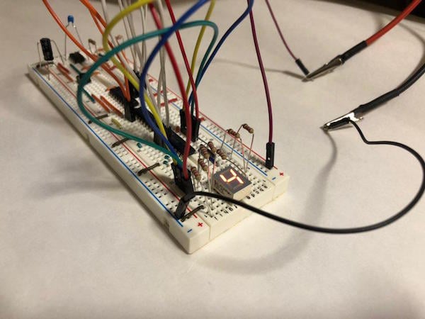
This is a very simple circuit to build and test.
The electronic dice connections on the breadboard.
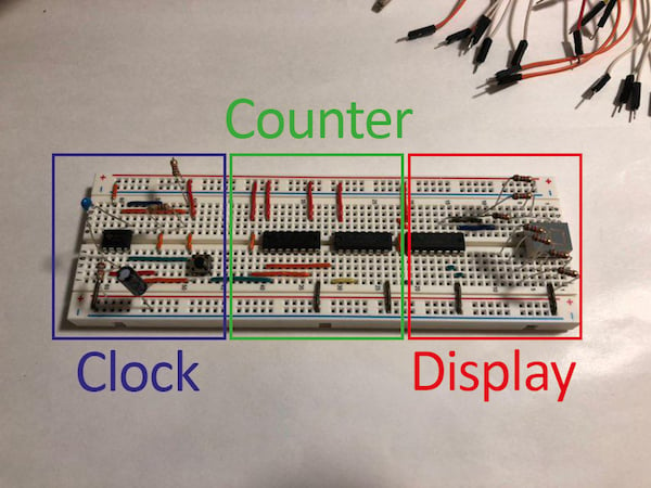
The circuit looks a bit messy after adding the data lines for the display, so here’s another image with the cables removed:
The final build without the connecting wires.