This project explains how to estimate a realistic lithium battery size for thin portable devices by combining runtime, power consumption, available space, peak load, and thermal requirements. It also shows how to turn those constraints into a practical battery specification before contacting a manufacturer.
An engineering workflow for turning runtime, power consumption, and enclosure space into a realistic lithium battery specification.
When designing a portable electronic product, battery selection often begins with a sentence like:
“We need a 3.7V 5000mAh battery.”
That sounds specific.
In practice, it may not be specific enough.
For thin devices such as portable monitors, handheld terminals, compact computers, smart instruments, medical electronics, and embedded AI devices, battery size is usually constrained by several things at the same time:
- available thickness
- available footprint
- required runtime
- average power consumption
- peak current
- charging architecture
- connector position
- thermal environment
A battery can meet the capacity target and still be unsuitable because it is too thick.
It can fit mechanically but fail to support the required peak load.
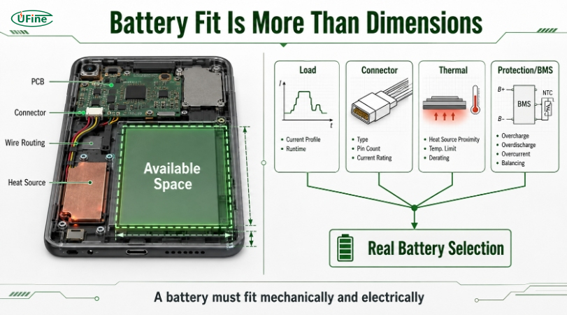
Or it can meet both requirements but leave no room for the connector, wiring, insulation, or protection electronics.
A better approach is to estimate the battery from the system requirements first.
This tutorial walks through a practical workflow.
Step 1: Start With Runtime, Not mAh
Before choosing a battery capacity, determine how much energy the device actually needs.
The simplest starting point is:
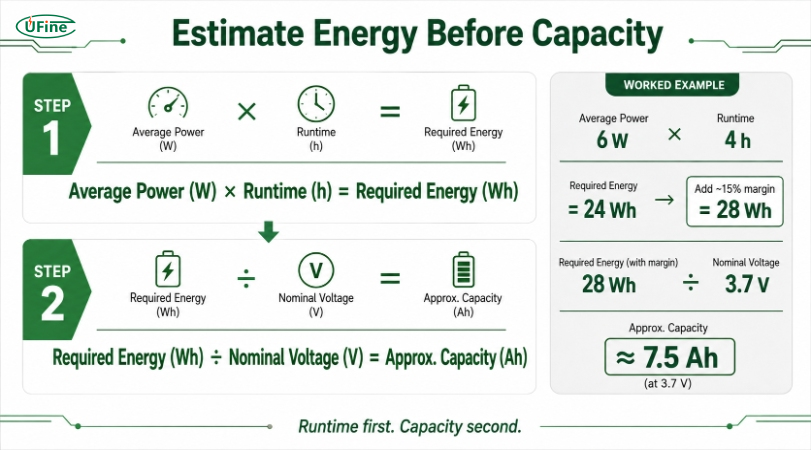
Required Energy (Wh) = Average Power (W) × Runtime (h)
Suppose you are designing a thin portable terminal with the following average loads:
| Component                                       | Average Power |
| ----------------------------------------------- | ------------: |
| Processor                                       |         2.5 W |
| Display                                         |         2.0 W |
| Wireless module                                 |         0.8 W |
| Sensors and peripherals                         |         0.4 W |
| Power conversion losses and miscellaneous loads |         0.3 W |
Approximate average system consumption:
6 W
If the target runtime is four hours:
6 W × 4 h = 24 Wh
So the theoretical battery requirement is approximately:
24 Wh
That is already more useful than saying:
“We need about 6000mAh.”
Why?
Because mAh does not describe total energy unless voltage is also known.
Step 2: Add an Engineering Margin
A theoretical energy calculation assumes a perfectly predictable system.
Real products are not perfectly predictable.
Power consumption can change because of:
- processor workload
- wireless transmission
- screen brightness
- temperature
- peripheral activity
- converter efficiency
- battery aging
- application behavior
For early estimation, engineers often add a reasonable design margin rather than sizing the battery exactly to the theoretical minimum.
For example:
Theoretical requirement: 24 Wh
If you initially allow roughly 15% additional energy:
24 Wh × 1.15 ≈ 27.6 Wh
So an early design target might be around:
28 Wh
This is not a universal rule.
The correct margin depends on the application, required end-of-life runtime, operating conditions, and system efficiency.
The important point is simple:
Do not design a production battery around the absolute minimum theoretical energy requirement.
Step 3: Convert Wh Into Approximate Capacity
Once you have an energy target, you can estimate the capacity required for a chosen battery voltage.
The relationship is:
Capacity (Ah) = Energy (Wh) ÷ Nominal Voltage (V)
For a simplified single-cell 3.7V example:
27.6 Wh ÷ 3.7 V ≈ 7.46 Ah
or approximately:
7,460 mAh
That immediately gives you a useful reality check.
If your mechanical design only has room for a very small pouch cell, a 7,460mAh target may be unrealistic.
That is exactly why energy calculations should happen before the enclosure is finalized.
Why Wh Is Better for Early Design
Compare these two specifications:
Battery A: 5000mAh
Battery B: 5000mAh
They look identical if you only compare capacity.
But if their nominal pack voltages differ, their stored energy differs.
For system-level design, Wh gives a much clearer picture.
That is also why engineers working with portable computers frequently consider laptop battery design requirements in terms of runtime, voltage architecture, space, load, and thermal conditions rather than looking at mAh alone.
Step 4: Measure the Real Battery Envelope
Now move from electrical design to mechanical design.
Open your CAD model and identify the area that can realistically be assigned to the battery.
Measure:
Maximum Thickness × Maximum Width × Maximum Length
For example:
Available cavity: 5 × 70 × 95 mm
Do not immediately send that exact size to the battery supplier as the required cell dimensions.
First check what else occupies the area.
Common space conflicts include:
- enclosure ribs
- screw bosses
- PCB edges
- speaker chambers
- antennas
- cable channels
- connectors
- thermal pads
- mounting structures
A rectangular empty region visible early in CAD often becomes smaller after the product architecture develops.
Step 5: Distinguish Enclosure Space From Cell Size
This is one of the most common mistakes in ultra-thin product development.
Suppose the enclosure provides:
4.0 mm of total internal height
That does not automatically mean:
Specify a 4.0 mm cell
The complete battery installation may also need space for:
- insulation
- adhesive
- packaging
- protection circuitry
- mechanical tolerance
- assembly clearance
The exact stack-up depends on the battery design and product construction.
A more useful mechanical question is:
“We have 4 mm total available internal height. What nominal battery thickness is realistic within this assembly?”
That gives the battery engineer room to evaluate the complete configuration.
Thickness Is Usually the Hardest Dimension
Width and length may sometimes be adjusted by moving nearby components.
Thickness is often fixed by the industrial design.
That means thin products usually benefit from discussing the battery before the enclosure thickness is frozen.
Once the mechanical stack-up is fixed, every fraction of a millimeter becomes harder to recover.
Step 6: Estimate Whether the Required Capacity Is Physically Plausible
At this stage, you know two important things:
Electrical requirement: approximately 28 Wh
Mechanical envelope: for example, 5 × 70 × 95 mm
Now ask:
Can this physical volume realistically support the required energy?
This is where simple calculators have limitations.
Battery capacity cannot be accurately predicted from external dimensions alone because real usable capacity depends on factors such as:
- cell chemistry
- electrode design
- packaging
- tab structure
- safety margin
- manufacturing process
- target current capability
However, volume is still a powerful early constraint.
If you reduce cell thickness significantly while keeping width and length unchanged, available internal volume decreases.
That generally reduces the capacity that can be achieved.
This creates a basic product-design relationship:
Thickness ↓ → Available Volume ↓ → Capacity Potential ↓
This relationship should not be treated as a precise linear formula.
It is simply a useful engineering constraint.
Step 7: Check the Load Profile
Capacity tells you how long the battery may run.
It does not tell you whether the battery can deliver the power the device needs.
Suppose your portable device has:
Average current: 1.0 A
but occasionally requires:
Peak current: 3.5 A
during:
- Wi-Fi transmission
- cellular transmission
- processor boost
- AI inference
- motor operation
- display startup
If you tell a supplier only:
“The device uses about 1A.”
you may hide an important part of the requirement.
A better specification is:
Continuous current: 1.2A
Maximum continuous current: 2A
Peak current: 3.5A
Peak duration: 2 seconds
Peak interval: approximately every 30 seconds
This helps the battery engineer evaluate not only the cell, but also the protection circuit, wiring, connector, and voltage behavior under load.
Step 8: Estimate Runtime With a More Realistic Power Profile
Real portable devices rarely consume exactly the same amount of power all the time.
Imagine this workload:
| Operating State     | Power | Time Share |
| ------------------- | ----: | ---------: |
| Idle/light workload |   3 W |        40% |
| Normal operation    |   6 W |        45% |
| Heavy processing    |  10 W |        15% |
You can estimate weighted average power:
3 × 0.40 = 1.2 W
6 × 0.45 = 2.7 W
10 × 0.15 = 1.5 W
Total estimated average:
5.4 W
For five hours of runtime:
5.4 W × 5 h = 27 Wh
Add the appropriate engineering margin and you have a much better starting point than simply guessing a battery capacity.
This method is particularly useful when designing:
- portable Linux computers
- AI terminals
- smart displays
- industrial handhelds
- communication devices
where power varies significantly by operating state.
Step 9: Don't Forget the Connector
A battery is not only a cell.
One of the easiest ways to create a prototype problem is to design the perfect battery footprint and forget the connector.
You should define:
- connector manufacturer
- connector series
- exact part number if known
- wire gauge
- wire length
- polarity
- cable exit direction
- mating connector
- required temperature sensor wiring
For example:
Connector: Molex, exact series TBD
Wire: 26AWG
Length: 50 ± 3 mm
Red: positive
Black: negative
Exit direction: toward PCB
A connector that exits from the wrong side of the battery can interfere with another component even when the cell itself fits perfectly.
The same applies to the protection PCB.
If the protection board is placed at the top edge of a pouch cell, the effective pack dimensions may be different from the bare cell dimensions.
Always ask for the dimensions of the final battery assembly, not just the cell.
Step 10: Consider the Thermal Environment
A battery can physically fit and still be placed in a poor location.
Compact portable devices often contain heat-generating components such as:
- processors
- GPUs
- charging ICs
- DC/DC converters
- SSDs
- wireless modules
- display electronics
If the battery is placed directly beside one of these components, the local temperature may be significantly different from ambient temperature.
So the battery supplier should know:
Charging temperature range
Discharging temperature range
Storage temperature range
and ideally:
Expected operating temperature near the battery
Do not simply specify:
Device operates from 0°C to 45°C.
If the battery is located beside a processor that creates a much hotter local environment, that information matters.
Step 11: Define the Charging Architecture
Before selecting the final battery, confirm how it will be charged.
Important questions include:
- What is the cell's nominal voltage?
- What is the required charge-voltage limit?
- What charge current will the system use?
- Is the charger designed for the selected cell configuration?
- Is power-path management required?
- Is temperature monitoring included?
- Where is primary protection implemented?
Battery and charger specifications must match.
Do not assume every lithium battery uses exactly the same voltage profile simply because it is described broadly as “Li-ion” or “Li-polymer.”
The charging design should be based on the actual cell specification.
Step 12: Build a Battery RFQ Before Contacting the Supplier
After working through the previous steps, you should have enough information to create a useful RFQ.
Instead of:
Need 3.7V 7000mAh lithium polymer battery. Please quote.
send something like this:
Application
Portable embedded computer
Mechanical Space
Maximum thickness: 5 mm
Maximum width: 70 mm
Maximum length: 95 mm
Electrical Requirements
Nominal voltage: 3.7V or supplier recommendation
Target energy: ≥28Wh
Average current: 1.2A
Maximum continuous current: 2A
Peak current: 3.5A
Peak duration: 2 seconds
Runtime
Target: approximately 5 hours under defined normal workload
Charging
System charger architecture under development
Temperature
Charging: 0–45°C
Discharging: -10–60°C
Interface
Connector: TBD
Wire length: approximately 50 mm
Cable exit: toward PCB
Project Information
Prototype quantity: 10 pcs
Estimated annual demand: 3,000 pcs
Target production date: TBD
This kind of specification gives a lithium battery manufacturer enough engineering context to determine whether an existing pouch cell can be used or whether a custom size, connector, protection configuration, or other modification needs to be evaluated.
Step 13: Prototype Before Freezing the Enclosure
A datasheet is not the same as a successful product integration.
Before committing to mass production, test the battery inside the actual device.
At minimum, verify:
Mechanical Fit
Does the complete battery assembly fit without compression or cable interference?
Connector and Polarity
Does the connector mate correctly?
Is polarity correct?
Is wire routing practical?
Runtime
Does the product meet the required operating time under the intended workload?
Peak Load
Does the device remain stable during the highest expected load?
Charging
Does charging behavior match the intended design?
Temperature
What happens during charging and maximum-load operation?
Assembly
Can production operators install the battery consistently without forcing cables or deforming other components?
A prototype that “powers on” is only the beginning of validation.
A Simple Design Flow
For future projects, you can summarize the process like this:
1. Define runtime
↓
2. Measure average system power
↓
3. Calculate required Wh
↓
4. Add an appropriate design margin
↓
5. Define voltage architecture
↓
6. Measure usable T × W × L
↓
7. Define continuous and peak current
↓
8. Define connector and wiring
↓
9. Review thermal conditions
↓
10. Ask the battery manufacturer to evaluate feasibility
↓
11. Prototype and validate
This workflow will not replace battery engineering.
It will make your first conversation with a battery engineer far more productive.
Common Mistakes to Avoid
Mistake 1: Starting With mAh
Start with energy and runtime.
Mistake 2: Using the Entire CAD Cavity as the Cell Size
Allow for the complete battery assembly and mechanical integration.
Mistake 3: Ignoring Peak Current
Average power does not describe every load condition.
Mistake 4: Specifying Only the Bare Cell Dimensions
Connector, wiring, protection components, and insulation also matter.
Mistake 5: Choosing the Battery After the Enclosure Is Finished
Battery volume should be discussed early enough that the product architecture can still change.
Mistake 6: Assuming a Higher Capacity Is Always Better
The best battery is the one that balances energy, power, dimensions, thermal conditions, safety, and manufacturability.