This project describes how to create a portable washing machine using HVPAK.
The system is designed using the HV macrocells and other internal and external components within the HVPAK to drive a 12 V DC-DC Motor. A Portable Washing Machine is a must-have when you need to wash a small number of clothes, when there is not enough space for a full-fledged washing machine, or when you are traveling and only have a 12 V battery. The proposed Washing Machine has three timer modes – 10 min, 20 min, and 40 min, these modes are switched with a rotary switch. In addition, this portable washing machine provides a constant number of revolutions per minute regardless of the load. The device can be powered with any 12 V voltage supply, it also has under-voltage protection with indication.
How does it work?
Step 1. Start with downloading free Go Configure Software Hub to open the.hv files and view the proposed circuit design. Use the development tools to freeze the design into your own customized IC in a matter of minutes. Renesas provides a complete library of application notes featuring design examples as well as explanations of features and blocks within the Renesas IC.
Our portable washing machine consists of a 10 L silicone collapsible bucket (Figure 1) and a 12 V DC-DC Motor with a pulsator wheel.
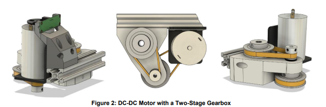
Attach a motor with a two-stage gearbox to the bottom of the bucket from the outside (Figure 2), and a pulsator wheel to the motor shaft inside.
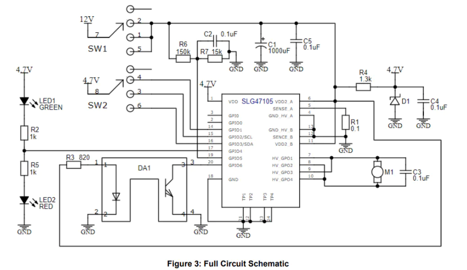
The Full Circuit Schematic of the Portable Washing Machine is shown in Figure 3.
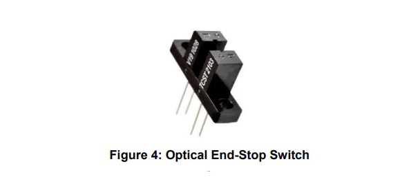
The SLG47105 sets the PWM to the motor to keep the rpm constant using feedback from an optical end-stop switch (Figure 4).
The green LED notifies about normal device operation. The red LED notifies about the end of the program. An alternate strobe of green and red LEDs means that the battery is discharged.
The device is powered with a 12 V voltage supply, the R4 resistor, and the D1 Zener Diode converts the voltage to ~ 4.7 V needed for an SLG47105.
Resistors R6 and R7 form the resistive divider for controlling the battery charge.
The resistor R1 is current feedback to avoid overcurrent.
The rotary switch SW1 is used to ON/OFF the device and switch timer modes - 10, 20, and 40 min.
Here is proposed a PCB design (Figure 5 and Figure 6) for this application, which is based on the schematic in Figure 3.
Step 2. HVPAK Design
The HVPAK design is shown in Figure 7.
The PWO0 block provides a ~100 kHz signal with a PWM depending on the motor`s rpm. The CNT2/DLY2 ensures stable functionality of the motor by smoothing the UP/DOWN motor speed signal. The CCMP0 checks the current on the HV OUT CNTR 0. If the current is higher than the maximum allowable current, the PWM Chopper 0 chops the PWM to avoid overcurrent. Then this final PWM signal goes to enable input of the HV OUT CTRLs blocks. They are both configured as Full Bridges. PIN 7 and PIN 9 are in parallel and connected to the first motor`s terminal. PIN 8 and PIN 10 are in parallel as well and connected to the second terminal. The DFF6 and MF3 form the signal of rotating duration and direction - 10 s for both directions. This signal goes to PH inputs of HV OUT CTRLs. The MF4 provides the delay of direction changing – 250 ms. This time is enough to create eddy currents of water and not overload the motor. Through this delay, HV OUT CTRLs, PWM0, and OSC1 are powered down due to a HIGH signal on the Sleep stage (3-bit LUT2). Input PIN 14, PIN 3, and PIN 17 are timer selectors of 10, 20, and 40 min, respectively. 3-bit LUT4, 4-bit LUT0, 3-bit LUT5, DFF2, DFF3, and MF0 provide selection functions depending on a chosen time mode and create a signal with the corresponding duration. After this time, the Sleep signal is HIGH and the system is powered down. The ACMP0 checks the VDD2 charge, if the voltage is less than 11.8 V the Sleep signal is HIGH and the system is powered down till the voltage is higher than 12.05 V. The 2-bit LUT3 is a selector for the LED state between the Pipe Delay signal and the timers` signal. The green LED notifies about normal device operation. The red LED notifies about the end of the program. An alternate strobe of green and red LEDs means that the battery is discharged.
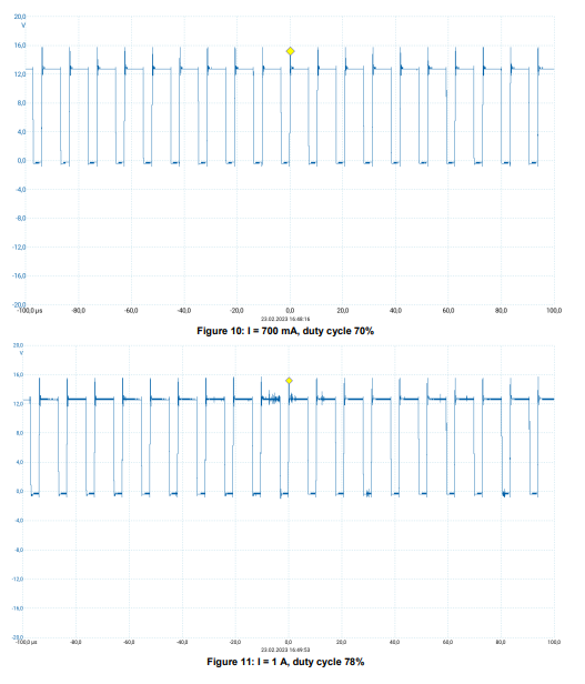
Step 3. Device Testing
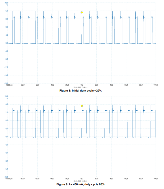
The following Figure 8 - Figure 11 shows the resulting signal on the PIN 7 and PIN 9 motor`s terminal. The supply voltage is 13 V.
Please, see also the video of the working Portable Washing Machine device.
Conclusion
This project provides a step-by-step guide on how to use the HVPAK as the control module for a Portable Washing Machine. The circuit has been tested and proven to function as expected with a 12V DC-DC motor.
Its internal resources, such as the HV, oscillators, logic, and GPIOs, are easily configurable to meet specific design requirements. The flexibility of the HVPAK allows for the efficient implementation of complex control functions, making it an ideal choice for a wide range of projects.