This project describes how to implement a traffic controller
Below we described steps needed to understand how the solution has been programmed to create the traffic signal controller. However, if you just want to get the result of programming, download GreenPAK™ software to view the already completed GreenPAK Design File. Plug the GreenPAK Development Kit to your computer and hit the program to design the solution.
Introduction
There often exist scenarios where flexible traffic signal sequences are required for the coordination of traffic through the intersection of a busy street and a lightly used side street. In such situations, the sequences can be controlled using different timers and a traffic detection signal from the side street. These requirements can be met through conventional methods e.g. using building blocks from discrete electronic components or microcontrollers. However, the concept of configurable mixed-signal integrated circuits (CMIC) provides an attractive alternative considering its design flexibility, low cost, development time, and convenience.
Many regions and countries are progressing to more complicated grids that can accommodate a greater number of variables to control traffic lights. However, many traffic lights still utilize fixed-time control, such as electro-mechanical signal controllers. The purpose of this project is to show how one can use GreenPAK's Asynchronous State Machine (ASM) to develop a simplified traffic signal controller to replace a fixed-time controller. This traffic signal regulates traffic passing through the intersection of a busy main street and a lightly used side street. The controller would control the sequence of two traffic signals, which are installed at the main and side street. A sensor signal, detecting the presence of side-street traffic, is fed to the controller that, in conjunction with two timers, would control the sequence of the traffic signals. A finite state machine (FSM) scheme is developed that ensures the requirements of the traffic signals sequence are met. The controller logic is implemented using a dialog GreenPAK SLG46537 configurable mixed-signal IC.
Requirements
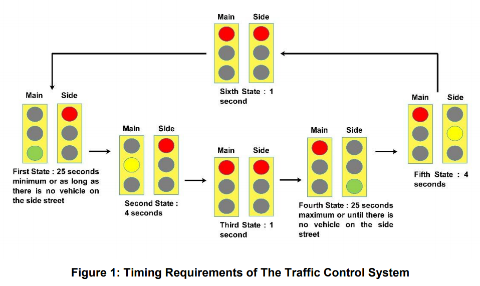
Consider a traffic scenario with the timing requirements of traffic signals from the main and side street, as shown in Figure 1. The system has six states, and will move from one state to the other depending upon certain predefined conditions. These conditions are based on three timers; a long timer TL =25 s, a short timer TS = 4 s and a transitory timer Tt = 1 s. Additionally, the digital input from side traffic detection sensor is required. A thorough description of each of the six system states and the state transition control signals is given below:
In the first state, the main signal is green while the side signal is red. The system will stay in this state until the long timer (TL = 25 s) expires or as long as there is no vehicle on the side street. If a vehicle is present on the side street after the expiration of the long timer, the system will undergo a state change moving to the second state.
In the second state, the main signal turns yellow while the side signal remains red for the duration of the short timer (TS = 4 s). After 4 seconds the system moves into the third state.
In the third state, the main signal changes to red and the side signal remains red for the duration of the transitory timer (Tt =1 s). After 1 second, the system moves to the fourth state.
During the fourth state, the main signal is red while the side signal turns green. The system will stay in this state until the expiry of the long timer (TL = 25 s) and there are some vehicles present on the side street. As soon as the long timer expires, or there is no vehicle on the side street, the system will transition into the fifth state.
During the fifth state, the main signal is red while the side signal is yellow for the duration of the short timer (TS = 4 s). After 4 seconds the system will move into the sixth state.
In the sixth and the last state of the system, both the main and side signals are red for the period of the transitory timer (Tt =1 s). After that, the system goes back to the first state and starts over again.
The third and sixth states provide a buffer state where both (main and side) signals stay red for a brief period of time during changeover. State 3 and 6 are similar and may seem redundant, however, this allows the implementation of the proposed scheme to be simple.
Implementation Scheme
A complete block diagram of the system is shown in Figure 2. This figure illustrates the overall structure, function of the system, and lists all the required inputs and outputs. The proposed traffic signal controller has been built around the finite state machine (FSM) concept. The timing requirements described above are translated into a six-state FSM as depicted in Figure 3.
The state-change variables shown above are:
Vs – A vehicle is present on the side street
TL – The 25 s timer (long timer) is on
TS – The 4 s timer (short timer) is on
Tt – The 1 s timer (transitory timer) is on
The Dialog GreenPAK CMIC SLG46537 has been chosen for the implementation of the FSM. This highly versatile device allows a wide variety of mixed-signal functions to be designed within a very small, low power single integrated circuit. Furthermore, the IC contains an ASM macrocell designed to allow the user to create state machines having up to 8 states. The user has the flexibility to define the number of states, the state transitions, and the input signals that will cause transitions from one state to another state.
Implementation Using GreenPAK
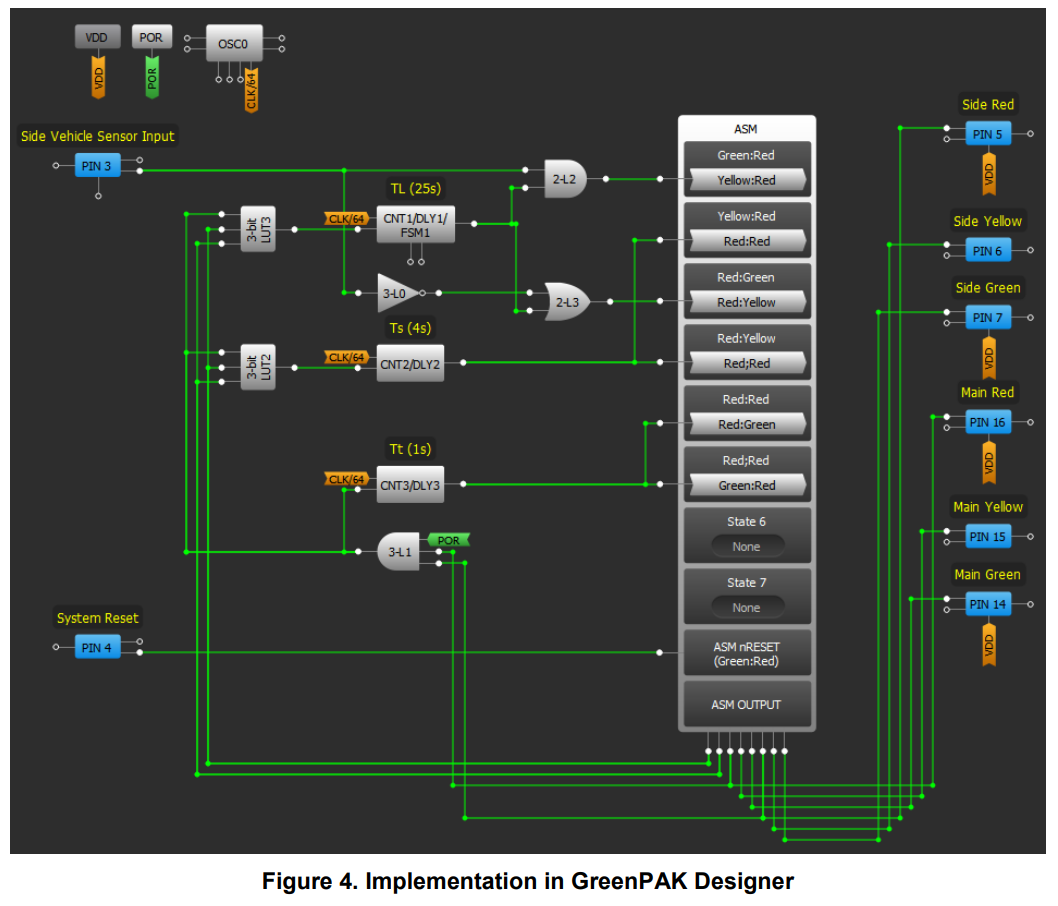
The FSM developed for the operation of the traffic controller is implemented using SLG46537 GreenPAK. In the GreenPak Designer, the scheme is implemented as shown in Figure 4.
PIN3 and PIN4 are configured as digital input pins; PIN3 is connected to the side street vehicle sensor input and PIN4 is used for system reset. PINs 5, 6, 7, 14, 15 and 16 are configured as output pins. PINs 5, 6 and 7 are passed to the side signal’s red, yellow and green light drivers respectively. PINs 14, 15 and 16 are passed to the main signal’s green, yellow and red-light drivers respectively. This completes the I/O configuration of the scheme.
At the heart of the schematic lies the ASM block. The inputs of the ASM block, which regulate state changes, are obtained from combinatorial logic using three counter/delay blocks (TS, TL, and TT) and the input from the side vehicle sensor. The combinatorial logic is further qualified using the state information fed back to LUTs. The state information of first, second, fourth, and fifth states is obtained using combinations of B0 and B1 outputs of the ASM block. The combinations of B0 and B1 corresponding to the first, second, fourth and fifth states are (B0 = 0, B1 = 0), (B0 = 1, B1 = 0), (B0 = 1, B1 = 1) and (B0 = 0, B1 = 1) respectively. The states information of the 3rd and 6th states is obtained directly applying the AND operator to the main red and side red signals. Feeding these states information to the combinatorial logic ensures that only the relevant timers are triggered. Other outputs of the ASM block are assigned to the main traffic lights (main red, main yellow, and main green) and side traffic lights (side red, side yellow, and side green).
The configuration of the ASM block is shown in Figure 5 and Figure 6. The states shown in Figure 5, correspond to the defined first, second, third, fourth, fifth, and sixth states shown in Figure 3. The output RAM configuration of the ASM block is shown in Figure 6.
The timers TL, TS, and TT are implemented using the counter/delay blocks CNT1/DLY1, CNT2/DLY2, and CNT3/DLY3 respectively. All these three blocks are configured in delay mode with rising edge detection.
As shown in Figure 3, the first and fourth states trigger TL, the second and fifth states trigger TS, and the third and sixth states trigger TT using combinatorial logic. As the delay timers are triggered, their outputs remain 0 until the configured delay completes its duration. In this way, the TL’, TS’, and TT’ signals are directly obtained from the outputs of CNT1/DLY1, CNT2/DLY2, and CNT3/DLY3 blocks. TS’ is directly fed to the second and fifth states transition input while TT’ is passed to the third and sixth states transition inputs. TL, on the other hand, is passed to combinatorial logic blocks (LUTs) giving the signals TL’ Vs and TL’+ VS’ which are fed to the transition inputs of the first and 4th states respectively. This completes the implementation of the FSM using the GreenPAK designer.
Results
For testing purposes, the design is emulated on the GreenPAK Universal Development Board using the SLG46537. The traffic lights signals (equated to digital output pins 5, 6, 7, 14, 15 and 16) are used to activate the LEDs that are already available on the GreenPAK Development Board to visually observe the behavior of the FSM.
In order to fully investigate the dynamic behavior of the developed scheme, we used an Arduino UNO board to interface with the SLG46537. The Arduino board provides the vehicle detection sensor input and system reset signals to the scheme while it gets the traffic light signals from the system. The Arduino board is used as a multi-channel logic analyzer to record and graphically show the temporal functioning of the system. Two scenarios that capture the general behavior of the system are developed and tested.
Figure 7 shows the first scenario of the scheme when some vehicles are always present on the side street. When the reset signal is asserted the system starts in the first state with only main green and side red signals on and all the other signals turned off. Since side vehicles are always present the next transition into the second state follows 25 seconds later turning on the main yellow and side red signals. Four seconds later the ASM enters the third state where the main red and side red signals remain on for 1 second. The system then enters the fourth state with the main red and side green signals turned on. Since the side vehicles are always present, the next transition takes place 25 seconds later moving the ASM to the fifth state. The transition from fifth to the sixth state occurs 4 seconds later as TS expires. The system stays in the sixth state for the duration of 1 second before the ASM reenters the first state.
Figure 8 shows the behavior of the scheme in the second scenario when a few side vehicles are present at the traffic signal. The behavior of the system is found to be functioning as designed. The system starts in the first state with only main green and side red signals on and all the other signals to be off 25 seconds later the next transition follows since there is a side vehicle present. The main yellow and side red signals are turned on in the second state. After 4 seconds, the ASM enters the third state with the main red and side red signals turned on. The system stays in the third state for 1 second and then moves to the fourth state keeping the main red and side green on. As soon as the vehicle sensor input goes low (when all the side vehicles have passed), the system enters the fifth state where the main red and side yellow are on. After staying in the fifth state for four seconds the system moves to the sixth state turning both main and side signals red. These signals remain red for 1 second before the ASM re-enters the first state.
Actual scenarios would be based on a combination of these two described scenarios which are found to be working correctly.
Conclusion
In this project, a traffic controller that can manage traffic passing through the intersection of a busy main street and a lightly used side street was implemented using a Dialog GreenPAK SLG46537. The scheme is based on an ASM that ensures the traffic signals sequence requirements are met. The behavior of the design was verified by several LEDs and an Arduino UNO microcontroller. The results verified that the design objectives were met. The key advantage of using the Dialog product is to obviate the need for discrete electronic components and microcontrollers to build the same system.
The existing design can be extended by adding an input signal from a push-button for the passage of pedestrians looking to cross the busy street. The signal can be passed to an OR gate along with the signal from the side vehicle input sensor to trigger the first state change. However, to ensure the safety of the pedestrian now there is an additional requirement of some minimum time to be spent in the fourth state. This can easily be accomplished using another timer block. The green and red signals on the side street traffic signal can now also be fed to the side pedestrian signals on the side street.