Design a bus using SelfCAD, a 3D modeling software.
I’m going to try to make a very simple bus, this is my first time using SelfCad but I’m going to try to use some of the skills I’ve been learning.
Before I start you should know that the area you’re looking at is called the scene. You look through the camera to see the scene. With nothing selected if you click on your cursor and move you will be able to change the view of your scene by moving your camera and look at your workspace at a different angle. This will be very helpful as you work.
First I’m going to place a cube in the center as the main part of my bus and I’m going to use the dimensions to make it longer, I’m going to make it 250 in depth. Then I will click confirm.
Keep in mind this will not be exact proportions, this is my first project and I’m just trying to practice some new tools.
Remember to re-name your mesh in the visualization tab on the right by double clicking.
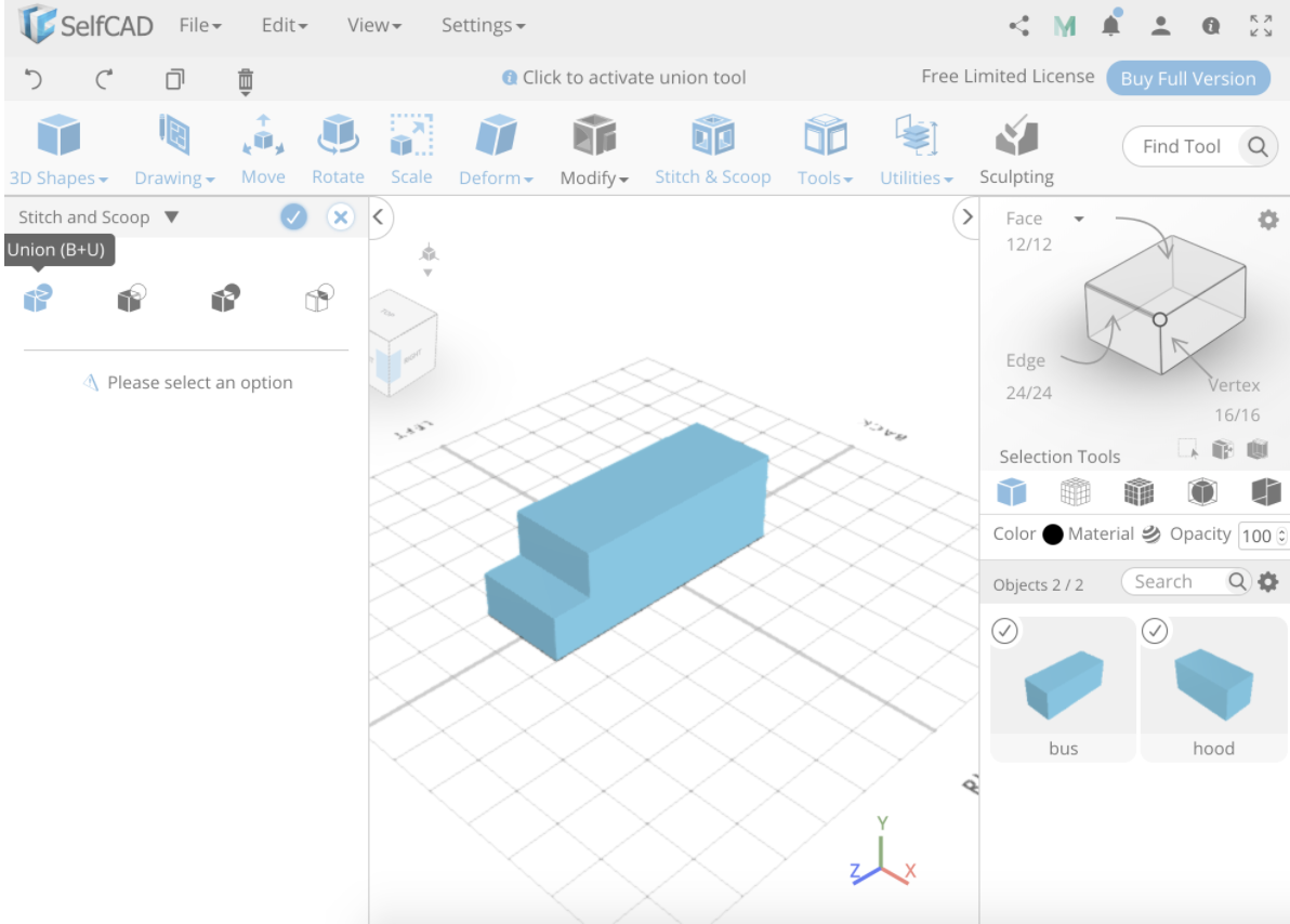
Then I will make another cube, about half the height of the first cube to be the hood of the bus. Then I will make the depth 50 and using the move tool and arrows bring the hood to the front of the bus.
Now I will select both cubes, use stitch and scoop, union, and combine both cubes to make it one bus.
Just to keep things neat, and as a useful tool to learn for the future, let’s select the bus, select move and there will be an option to center object. Click that so things will be centered and easy to work with.
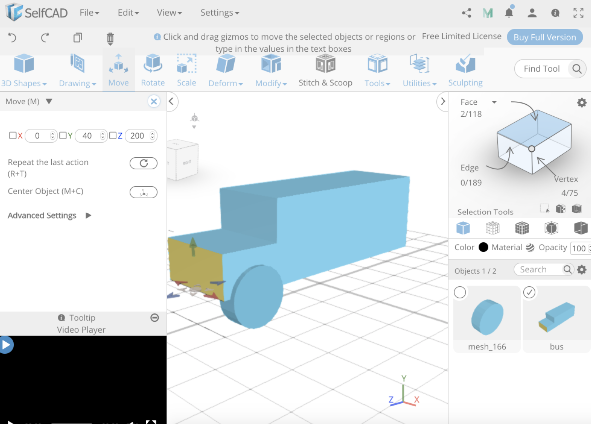
Because we’re going to want to add some wheels to this bus, select the now one shape, click move and in the Y position change it to 40 to raise our bus off the floor.
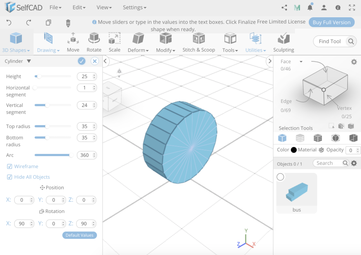
Now I’m going to make a wheel, click on shapes and pick a cylinder, before we choose positions and sizing we’re going to make sure to hide all objects so we can see what we’re doing.
Because the width of the bus is 100 we’ll make the height of the cylinder 25 so when we put it on it’s side it’ll look like it fits. We’ll also make the bottom and top radius 35, that’s just a guess for now but we can always switch it later if we don’t think it fits correctly. Then we will rotate the X and Z positions by 90 degrees to get it in the right direction we want it.
Now that we have clicked confirm we will rename our shape to “front left wheel” and move it to where we want it which is right under the hood of our bus, let’s position it so the wheel is sticking out of the width of the bus by a little so we can see it well.
I see now that we didn’t make the hood of the bus big enough so in the visualization window I’m going to select “face” selection, select the front of my hood and move it forward with the move tool until the wheel fits.
When nothing is selected, move the camera around to make sure the wheel fits to your liking.
After, let’s move the position of your camera so you’re looking head on at the front of your bus.
Before we go to make our second wheel, we should check the placement of our first wheel for the next step. For me it’s at X position 45.
Now for the next front wheel we will select the wheel, click tools and copy offsets. Now drop down Advanced Settings and on the bottom, to make the macro, hit save which will save the size and position of the shape we are currently selecting (along with any other changes you may have made to the shape). Once you have made the macro, load that in the ‘load macro’ part right on top of it. You may also change the name of the saved item to make things more neat, just double click on the blue macro word and rename it to wheel. Now we will change the position of the X to -90 so it will match our first wheels position and click copy. Then rename that shape to ”front left wheel”.
We moved it to -90 because it is 45 spaces from the center and then an additional 45 spaces to the left to make it even and we want it to go in the left direction so we made it negative.
Because we centered the bus, it should be in the center of your workspace and so having the wheels in positive and negative positions but the same number will make sure they’re even.
If you moved the bus since we centered it, you can select all objects, click move and there will be an option to center object, if all objects are selected they will all move together to the center.
Now let’s position the camera so you can see the length of the bus again.
For the back wheels we’re going to try another technique. Let’s select both front wheels, by clicking on the first wheel, holding down shift and clicking the other. After, click on the move tool or hit ‘M’ then hold down the control button for Windows or command for Mac and using the arrows move the wheels to the back of the bus. Because this bus isn’t realistic you can place the wheels to your liking. Then of course rename the back wheels.
Now let’s put in some windows.
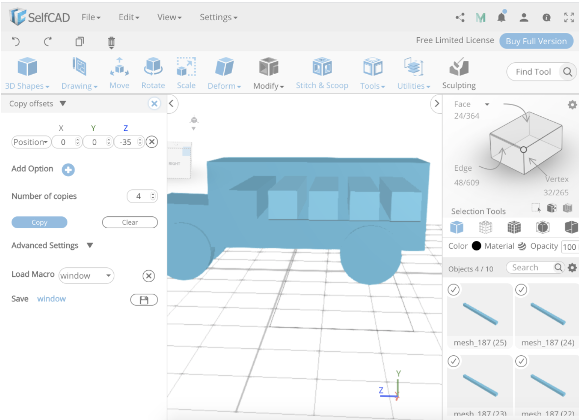
Drop in a new cube. This time we don’t want to hide all object because we’re going to use our bus as a reference size. Make the width significantly bigger than the bus, it doesn’t matter how much bigger but we want to see that it goes through the bus to the other side. We will make the height and depth 25 so we can have a nice square window and click confirm.
Change the position again so you’re looking at the length of the bus. Let’s use the move tool to move our window where we want it, Y at 100 and Z at 20 looks good to me.
Now let’s use the copy offsets tool again, make sure our window is selected, make the new macro of "window", load the macro of window and let’s make 4 copies and put them -35 Z apart from each other.
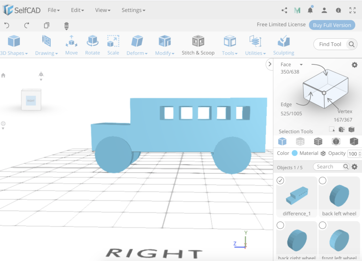
Keep those windows selected and reselect the first window also because after you copied, it will have deselected, and also select the bus. Now click stitch and scoop, choose the second option which is difference, in 'select objects to subtract' choose your 5 windows and you will see it has cut out the windows from the bus. Now click confirm.
Our last step is we’re going to join the wheels to our bus and make it one object ready to 3D print or use as wanted.
Select all objects, click stitch and scoop, union and click confirm.
Here we have our finished basic bus!
Great job everyone!