An antenna tuner is an impedance matching network that connects the transmitter and the antenna.
The antenna tuner plays a very important role in short-wave radio communications. Due to different antennas and operating frequencies, the impedance presented by the antennas can vary greatly. The impedance mismatch caused in this way will cause great loss to the signal transmission, and even cause the transceiver to malfunction or be damaged. In addition to increasing the strength of the signal, the antenna tuning device can reduce the spurious response of the receiver. This is because it is a tuning transformer, which improves the RF selection of the receiving device.
Schematic Diagram
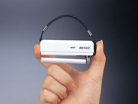
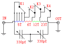
Figure 1 shows the schematic diagram of the antenna tuner circuit, and Figure 2 shows the actual diagram. It can be seen from the figure that the structure is very simple. In fact, almost all antenna tuner structures and principles are the same. The difference is the control method. Most of the finished products adopt the closing of automatic control switches to achieve the purpose of tuning. Because of its detection circuit, the control circuit and coding method and interface do not have a universal protocol. Therefore, most models cannot be operated concurrently, and are only used for a certain transceiver.
Figure1. schematic diagram of the antenna tuner circuit
Figure 2. the actual diagram
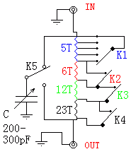
Figure 3 shows an antenna tuner that uses a variable capacitor but adds a toggle switch. I actually prefer this structure. Because it is easier to adjust during use. And it works equally well.
Figure 3. an antenna tuner that uses a variable capacitor
How to make:
L is a hollow coil, and a 1.2mm (Pm = 100-500W) high-strength enameled wire is wound on a 25mm diameter skeleton. A space of 2mm is made between the loops to easily lead a joint in the coil.
The capacitor uses a 330PF air-diode radio tuning capacitor. The key to choosing is to consider its power capacity. That is, the distance between the capacitor's dynamic and static plates must be large enough to avoid a breakdown during high-power operation. If you use a dual-tuning capacitor for an ordinary radio, you can properly remove several moving and stationary pieces in the middle to increase the distance, and then use them in parallel.
The above circuit should have very good shielding, and the aluminum lunch box is a good choice. A better method is to use a section of a suitable aluminum alloy square. One section is the main body, and the other section is cut along the diagonal to form two side baffles.
How to use:
It should be used in conjunction with a standing wave ratio meter. Firstly adjust the capacitance to the minimum, then adjust the inductance to maximize the forward power, that is, the minimum standing wave, and then adjust the capacitance to maximize the forward power.


