This article describes how to create a smart lamp with brightness intensity control and motion sensor using HVPAK.
Introduction
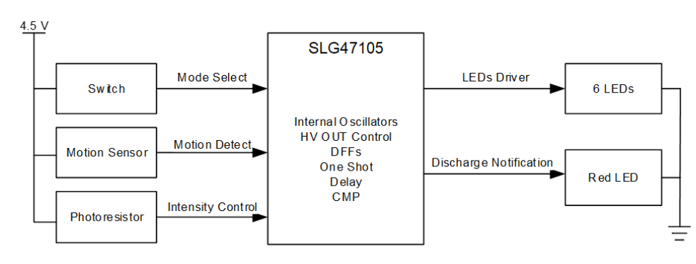
In this article we reveal how to design a smart brightness-controlled lamp with a motion sensor using the SLG47105V. The system is designed using the HV macrocells and other internal and external components within the GreenPAK to interact with a motion sensor.
The lamp has two modes: the intensity-controlled and the night mode. In the intensity-controlled mode, the light becomes brighter when the ambient light decreases and vice versa. In the night mode, the brightness is constantly dim. The light turns on only when the motion is detected by the PIR motion sensor. The lamp is powered with 3 AAA batteries (summary 4.5 V) and it has a red LED blinking signal to notify about batteries discharging.
The design can be used as additional lighting in the closet, in the hallway, in the garage, and so on.
The complete design file is available here. It was created in Go Configure™ Software Hub. More application notes you may find here.
Construction and Operating Principle
Block Diagram
The Block Diagram is shown in Figure 1.
Mode Select
The design consists of six main parts.
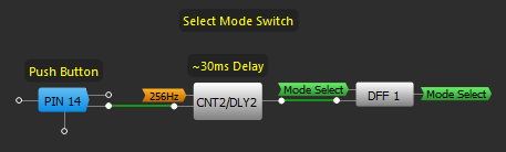
The first one is Mode Select Switch. The part of the GreenPAK design is shown in Figure 2.
Figure 2. Mode Select Switch Design
The Mode Select Switch is LOW until pressing the button. Then the signal goes to DFF1, where the signal is latched before the next pressing. So, Mode Select has two states: LOW and HIGH, which are changed by pressing the button.
Then, the Mode Select signal goes to Mode Select part. The part of the GreenPAK design is shown in Figure 3.
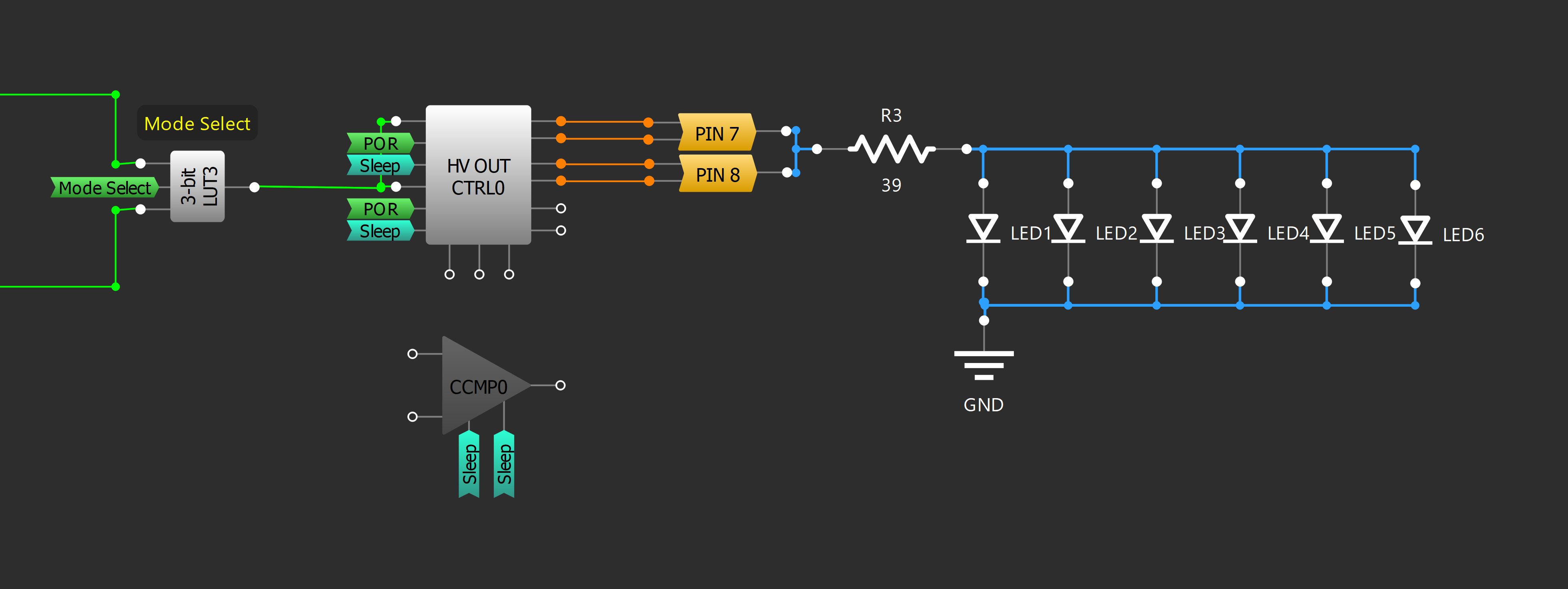
When the Mode Select is Low, the Output of LUT3 is the Output of Intensity-Controlled Mode, when the Mode Select is High, the Output of LUT3 is the Output of Night Mode.
Night Mode
The Night Mode is a stable PWM signal with the Duty Cycle of ~12.5 % and 64 Hz frequency (Figure 4).
Intensity-Controlled Mode
The design of the Intensity-Controlled Mode is shown in Figure 5.
Figure 5. Intensity-Controlled Mode
The idea is to create a Schmitt Trigger Oscillator using PIN 2, PIN 3, Inverter, and a Resistor. In this case, the 10 M (dark resistance) photoresistor is used instead. It means that the frequency of the Oscillator depends on the value of the resistance. When the ambient light increases, the resistance decreases, and when it becomes darker, the resistance increases. Accordingly, when the resistance increases — the frequency decreases, and vice versa.
Then, this signal is used as data for the One-Shot macrocell (CNT4).
Since the clock — 8.3 MHz and the inverted One-Shot Pulse Width — 10.9 us are constant, the output signal results in PWM with a constant 10.9 us of LOW and the rest period of HIGH depending on the frequency generated by the Schmitt Trigger Oscillator with a photoresistor.
LED Driver
When the Mode is selected, the LUT3 output signal goes to HV OUT CTRL to drive the 6 LEDs connected in parallel. It is configured as Half-Bridge in Pre-Driver Mode (Figure 6) to provide the necessary current of 120 mA.
Motion Sensor
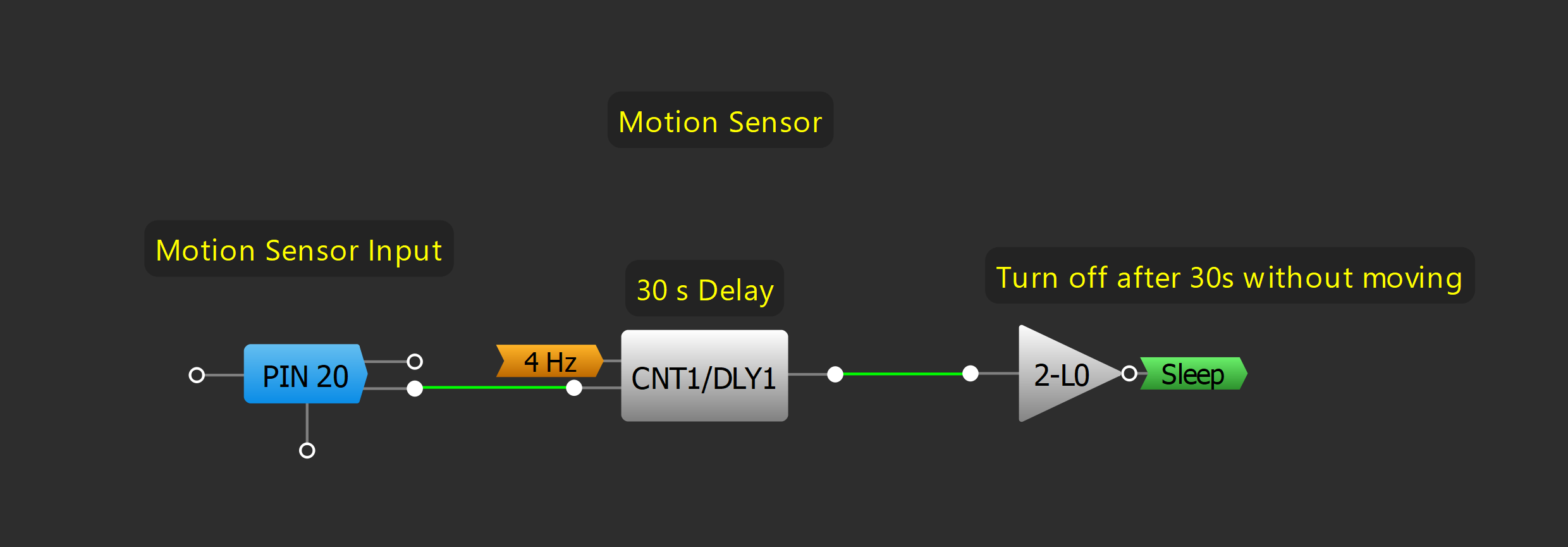
The lamp has a PIR motion sensor to decrease power consumption. The configuration can be found in Figure 7.
The CNT1 counts 30 s of Motion Sensor output. When the Sensor output is LOW more than 30 s — HV OUT CTRL and Oscillators are powered down with a HIGH Sleep signal (see Figure 8).
Figure 8. Oscillators Configuration
Battery Discharge Notification
As the lamp is powered by 3 batteries of 1.5 (4.5 V), the device needs a Battery Discharge Notification which helps the user not to forget to change batteries. The configuration can be found in Figure 9. The Analog Comparator CMP0 with 0.5 gain compares VDD and reference voltage. If this voltage is smaller than 1952 mV, it is time to change batteries because the voltage has already decreased to 3.9 V. In this case, the red LED starts blinking with a 25% duty cycle notifying about discharge.
Figure 9. Battery Discharge Notification
The full circuit design can be found in Figure 10.
Figure 10. Full Circuit Design
Device Testing
To test the design, the circuit is connected to 5V (VDD, VDD_A, and VDD_B).
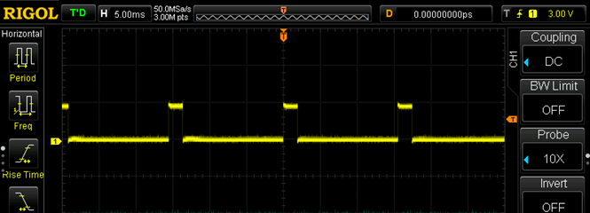
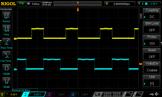
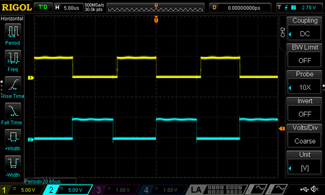
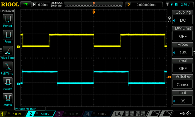
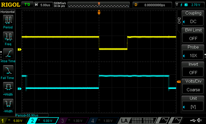
The oscilloscope screenshots show the Schmitt Trigger Oscillator signal (PIN 2, GPIO 0) in blue and the Intensity-Controlled Mode output (PIN 7, HV_GPO0_HD) in yellow (Figure 11 — Figure 15).
As can be seen from these figures, the Duty Cycle of Intensity-Controlled Mode increases (decreases) when the Period of Schmitt Trigger Oscillator increases (decreases).
Figure 11. Period of the Schmitt Trigger Oscillator — 12.2 us
Figure 12. Period of the Schmitt Trigger Oscillator — 16.9 us
Figure 13. Period of the Schmitt Trigger Oscillator — 20.65 us
Figure 14. Period of the Schmitt Trigger Oscillator — 29.45 us
Figure 15. Period of the Schmitt Trigger Oscillator — 55.9 us
The results prove that the circuit works as expected, and the HV GreenPAK is capable of acting as the control module for LEDs.
Conclusion
The article describes how to configure the HVPAK to create a Smart Brightness-Controlled Lamp with Motion Sensor. It works only when the motion is detected and has two modes. The Night Mode has a constant low brightness. The Intensity-Controlled Mode varies depending on the ambient light. In addition, the Smart Lamp has a Battery Discharge Notification.
The GreenPAK’s internal resources, including the HV, oscillators, logic, and GPIOs are easy to configure to implement the desired functionality for this design.