In this project, SLG46620V is used in a car safety system application as the ADC and preprocessing unit of a system
Below we described steps needed to understand how the solution has been programmed to create a tire pressure sensor. However, if you just want to get the result of programming, download GreenPAK™ software to view the already completed GreenPAK Design File. Plug the GreenPAK Development Kit to your computer and hit the program to design the solution.
Introduction
Newer cars typically feature a tire pressure monitoring systems (TPMS) that will warn the driver when a tire is significantly under-inflated. This safety feature was deemed important enough that the United States Department of Transportation (DOT) and the National Highway Traffic Safety Administration (NHTSA) published a Federal Motor Vehicle Safety Standard. Tire pressure affects a vehicle's fuel economy, handling, and possible catastrophic tire failure. In this project, over-inflated detection is also included. The system may also be used for anti-theft, warning when one of the sensors is not sending information (in that case, one of the tires may have been stolen).
There are two TPMS system types. One of them is called Direct System. It is based on installing a pressure sensor in each wheel to directly measure the pressure in each tire, sending the information to the vehicle's on-board computer which warns drivers when the air pressure in any of their tires drops at least 25% below the recommended cold tire inflation pressure, or if the tire has 25% over the recommended inflation pressure.
Direct systems are typically more accurate and reliable, and most are able to indicate which tire is under-inflated.
The other system is called Indirect System. It uses the vehicle's anti-lock braking system's wheel speed sensors to compare the rotational speed of one tire versus the others. If a tire is low/high on pressure, it will roll at a different number of revolutions per kilometer than the other three and alert the vehicle's on-board computer. Indirect systems are unable to generate accurate readings in cases where all four tires are losing pressure at the same rate, such as the effects of time and temperature.
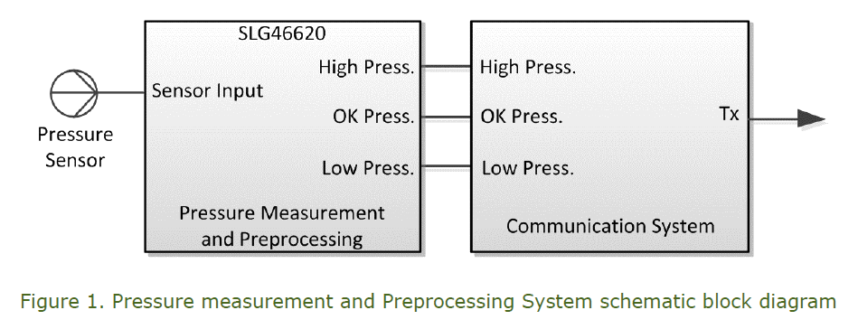
In this implementation, the Direct Tire Pressure Measurement System will be used. In this case, the pressure will be measured and analyzed locally on each tire with the SLG46620V, sending the information of under-pressure, over-pressure or correct pressure to the central system (onboard computer or dedicated system) via the communication system (Figure 1). With this implementation, a TPMS may also be retrofitted on older cars by adding a small central system to the console of the car.
Pressure Sensor
In this type of application, choosing the correct sensor is one of the most important stages in the design. An automotive application not only requires a sensor with the correct resolution and pressure range, but it also requires certified sensors that are able to be used for automotive safety applications and with low current consumption.
In this case, there are two options for the type of sensor: Differential Pressure Sensors and Absolute Pressure Sensors. Differential ones measure the difference between the actual pressure and the atmospheric pressure. Absolute ones use absolute zero as its reference pressure, measured relative to a full vacuum (outer space).
Since absolute pressure uses absolute zero as a definitive reference point, absolute pressure remains precise and accurate regardless of changes in ambient or process temperature. This is the main reason for choosing Absolute Pressure Sensors.
The selected pressure sensor for this application is the SM5420C-060 from SMI Pressure Sensors. It is an absolute pressure sensor with an operating pressure range of 0 to 60 PSI. The power supply must be 5V (compatible with SLG46620V) and with a current low consumption of 1mA. One of the advantages of this sensor is that it is certified to be used for automotive applications, being qualified to meet AEC Q100 standards (the Automotive Electronics Council standard about Failure Mechanism-based Stress Test Qualification for Integrated Circuits).
The selected pressure sensor has a differential output proportional to the measured pressure and it can be modeled as:
The output circuit can be thought as a Wheatstone bridge, as it can be seen in Figure 2.
Most important characteristics of the sensor are shown in Table 1.
Schematic Diagram
Due to the differential outputs of the sensor, and considering the simpler way for conditioning the signal for being acquired by SLG46620V’s ADC, the external implemented circuit is shown in Figure 3.
The signal conditioning circuit can be divided in two parts to describe it.
First of all, the differential output of the sensor (out+ and out–) is converted to a single ended signal with the operational amplifier U1. This is done by a typical differential configuration with unity gain. With this circuit, the signal obtained at the output of U1 is:
It’s important to mention that, if pressure is zero, the output voltage is zero.
That’s why the operational amplifier must be a rail-to-rail operational amplifier.
The other part of the design is the second operational amplifier (U2). It is required to condition the level of the signal to meet the input specifications of the SLG46620V analog-to-digital converter.
SLG46620V, in the electrical specifications of the datasheet, specifies that the ADC with the single-ended configuration must have a minimum voltage input of 30mV/G (where G is the gain of the Programmable Gain Amplifier of the ADC) to acquire the signal. To obtain this minimum level voltage, the second operational amplifier adds Vmin voltage to the single-ended signal coming from the sensor and the first operational amplifier. With this configuration, the output signal (Vout) can be directly connected to the analog input of the SLG46620V.
When the specifications of the ADC are considered, the maximum input level voltage in single-ended mode is 1030mv/G. If the worst case is analyzed, the maximum differential output level of the sensor can be 135mV. In this case, it can be risky if the Gain is configured to 8 (because the maximum input level is 137mV) because low pressures may not be compatible with the minimum input voltage of the ADC.
For this reason, the ADC and the PGA are configured with a gain of 4. With this configuration, Vmin must be between 23mV and 99mV. The selected value is 60mV, so the output range of the conditioned signal is 60mV to 195m. The Vmin voltage is obtained from the SLG46620V DAC, connecting its output to one of the GPIOs.
Implementation
As described above, the pressure measurement described in this project is part of a car safety system. The aim of this implementation is to get benefits of the small size and low current consumption of the SLG46620V, allowing to measure and process the pressure locally.
Another important benefit of this implementation is the speed of processing. Considering the timing requirement of the NHTSA standard, the SLG46620V processes the sensor data very fast, so the onboard computer is free to make all the necessary verifications before reporting low or high pressure.
The GreenPAK circuit design implementation is shown in Figure 4.
The single-ended signal from the sensor is obtained from PIN 8, which connects to the input of the PGA. The PGA configuration is shown in Figure 5. It shows the PGA configured in Single-Ended Mode with a Gain of 4 and it’s always powered on.
The output of the PGA is connected to the Analog to Digital Converter. The configuration of the ADC is a single-ended mode, with the RC oscillator as the ADC clock as shown in Figure 6. With this clock configuration, the ADC sample rate is 1.56 ksps.
The ADC conversion is analyzed with the DCMP/PWM blocks. DCMP0 compares the pressure with the low limit, indicating when the pressure is lower than the configured value with a low level on its OUT+ output. The DCMP/PWM 0 block is configured as DCMP, comparing the positive input with the value stored in Register 0.
DCMP2 compares the pressure with the high limit, indicating when the pressure is higher than the configured value with a high level on its OUT+ output. The PWM/DCMP 2 block is configured as DCMP, comparing the positive input with the value stored in Register 2.
DCMP0 configuration is shown in Figure 7. The configuration of DCMP2 is the same as the configuration of DCMP0.
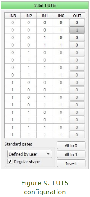
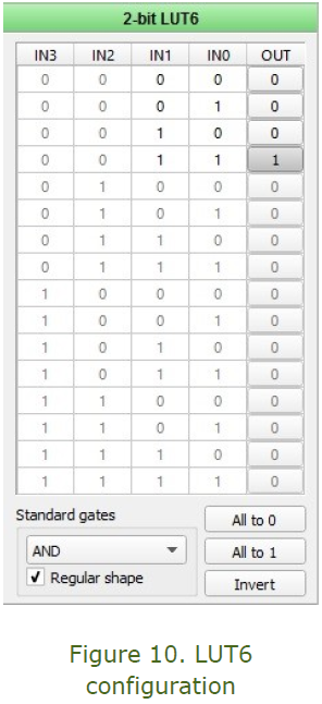
To determine the outputs of the system, 2-bit LUT4, LUT5, and LUT6 are used. LUT4 output is high only when low pressure is detected (low level at OUT+ of DCMP0 and at OUT+ of DCMP2). LUT5 output is high only when the correct pressure is detected (the high level at OUT+ of DCMP0 and low level at OUT+ of DCMP2). LUT6 output is high only when high pressure is detected (the high level at OUT+ of DCMP0 and high level at OUT+ of DCMP2). Figures 8 to 10 show the configurations of 2-bit LUT4, LUT5, and LUT6.
The output of 2-bit LUT4 (Low-Pressure output) is connected to Pin 16, the output of 2-bit LUT5 (Correct Pressure output) is connected to Pin 17 and the output of 2-bit LUT6 (High Pressure output) is connected to Pin 18.
DAC0 is included in the design as the voltage reference Vmin. It is configured to generate 60mV and is connected to GPIO19 via the VREF0 block. Its configuration is shown in Figure 11.
Test and Conclusions
To test the implementation, a linear ramp of pressure was applied to the sensor, from low pressure to high pressure along with the analyzed range. To analyze the results, pins 16 to 18 (in this order) were logged with a logic analyzer. These outputs can be seen in Figure 12.
It can be seen that the system is tested for the three possible states, obtaining a high level on the corresponding output pin of the SLG46620V.
Conclusion
In this project, SLG46620V is used in a car safety system application as the ADC and preprocessing unit of a bigger system. We have shown how to condition the signal to meet the ADC and PGA specifications of the GreenPAK and the entire implementation is described. It is important to mention that the values used to compare the ADC conversion can be changed for different car tire models, without changing the logic of the system.