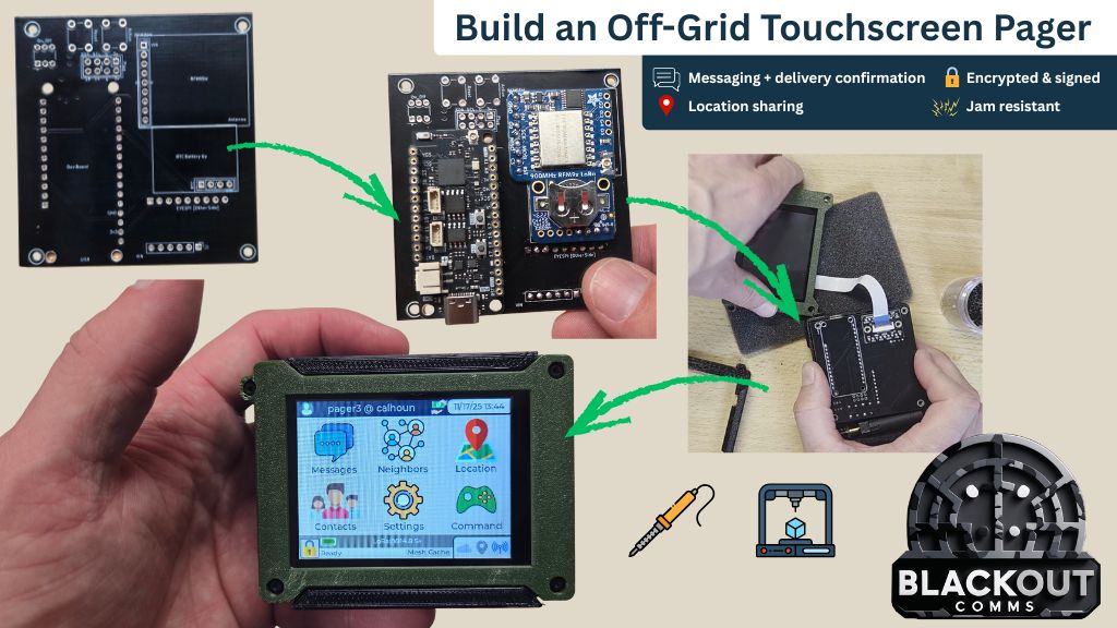
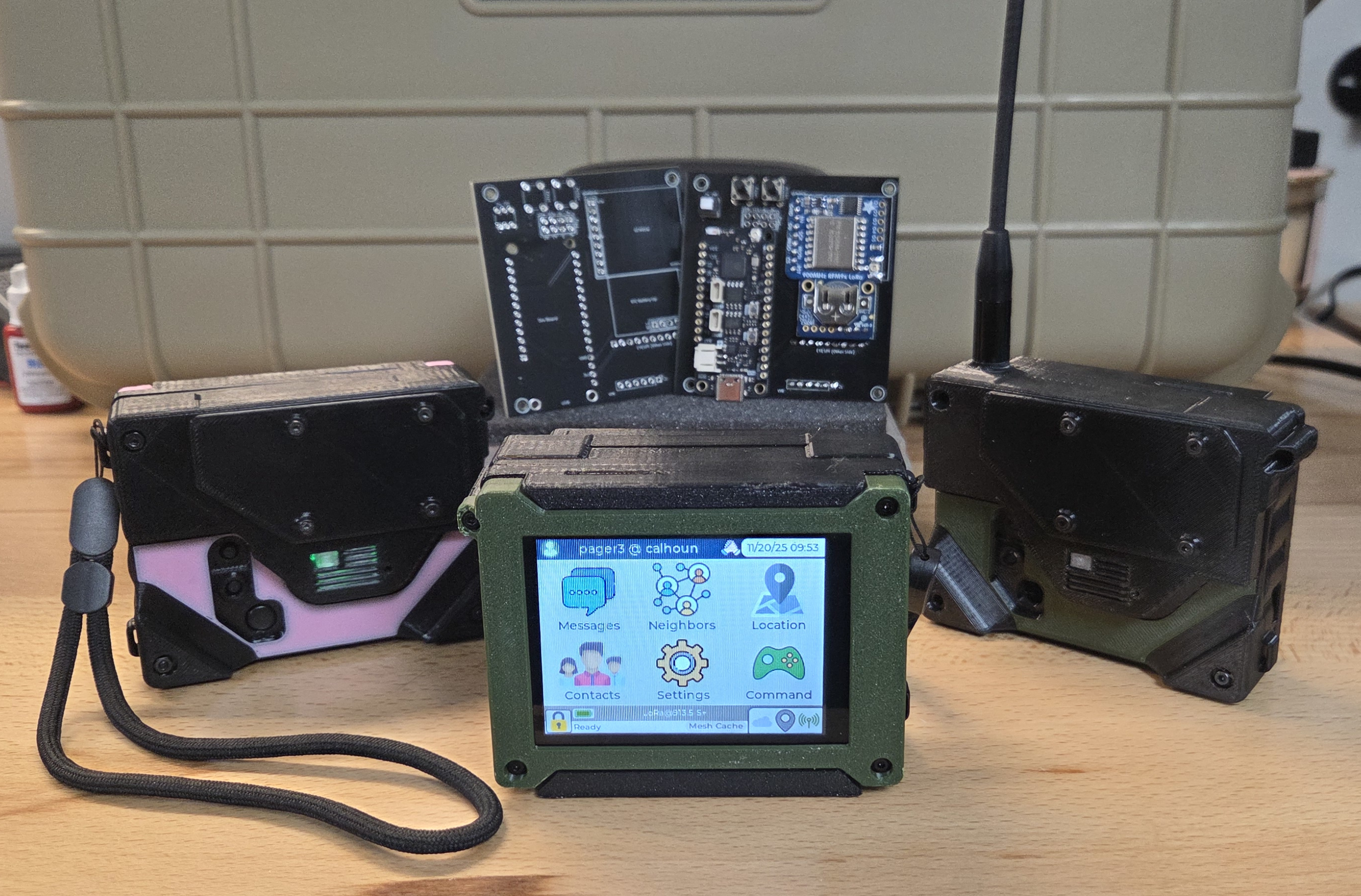
This LoRa / mesh-enabled touchscreen pager lets you text & share location within your private mesh network. These pagers are encrypted, jam-resistant, and have a direct range of 3-6 miles (rural) with the low profile internal antenna build. Longer distances are possible with meshing and/or external antennas.
These work with no grid & no phone!
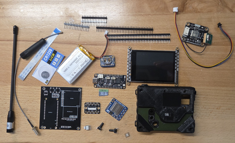
Required Components
The pager is composed of a PCB, several Adafruit components, a 3D printed case, and optionally GPS.
Required Components
Optional Components
GPS is recommended, but it does make the pager a little thicker. If you want vibrate alerts, you'll need the haptic driver. Currently the 3D printed enclosure doesn't allow room for both, but the firmware can support either, both, or neither.
Assembling the Pager "Core"
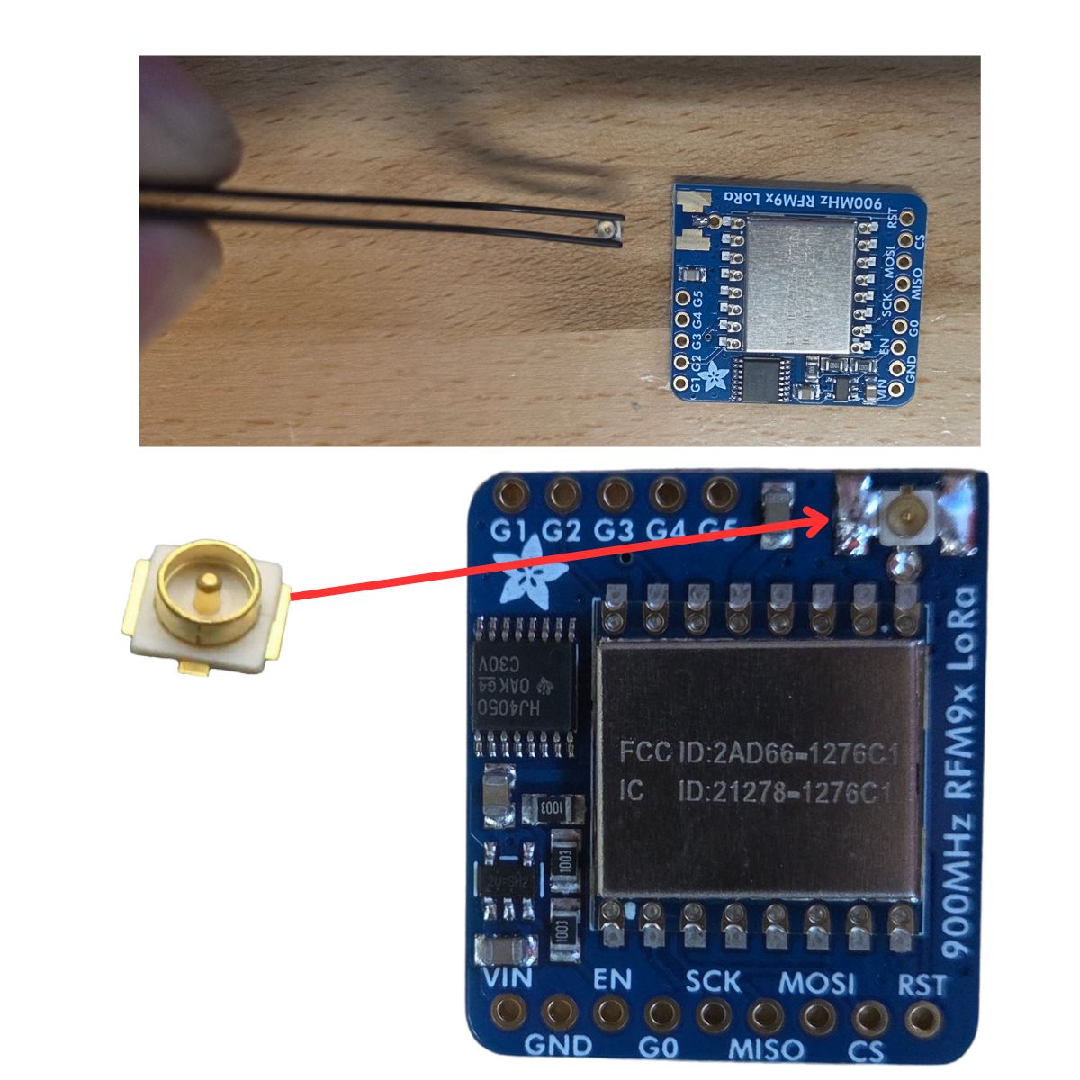
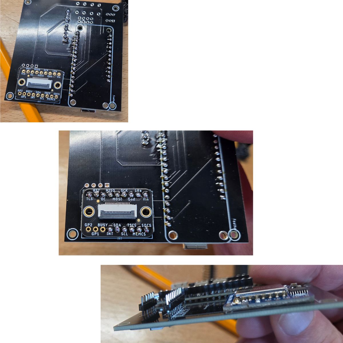
Add IPEX Connector to RFM9x Board
This can be challenging, I use reading glasses and a set of soldering tweezers. The technique I use is to put a small bit of solder onto the antenna (middle) connection of the PCB (shown on the image here). Then I use tweezers to hold the connector properly on the hardened solder and re-melt it.
Lastly, I solder the two ground connections into place, and add a little more solder to the middle connector, which leaves it looking like the image at the bottom. It may take a few tries the first time, which is fine. Be sure not to short the +/- (middle and outer) connectors on the antenna.
Test connectivity by testing for continuity between any ground (the big silver cover works) and the IPEX ground, as well as continuity between the pin inside the IPEX connector and the ant connection co the RFM chip (the pin hole, upper right, near the "R" in LoRa.
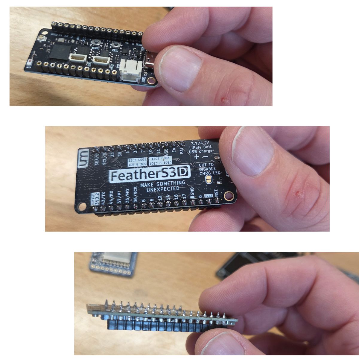
Prepare the ESP32S3 Feather with Short Pins
Trim two short header pin strips to the proper number of pins for the feather. Solder the short pins to the feather, female end of the pins facing up, as shown. The pins should protrude from the bottom of the feather somewhat as shown. Make sure excess solder is removed from these protruding pins so they can be inserted into the pager PCB.
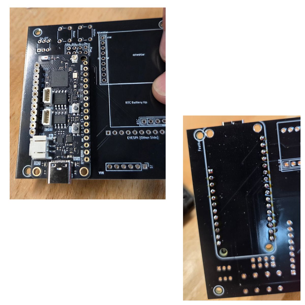
Add the Feather to the Pager PCB
Place the pager onto the pager PCB as shown. Solder each pin to fully connect the feather to the PCB. Be sure to use plenty of solder. You may need to keep the pin/hole heated for several seconds to allow time for solder to pool inside the the hole as necessary.
Later on, if you have any connectivity problems when running the firmware for the first time, it's likely either one of the pins here isn't fully soldered, or another component added to the PCB may not be fully connected (not enough solder).
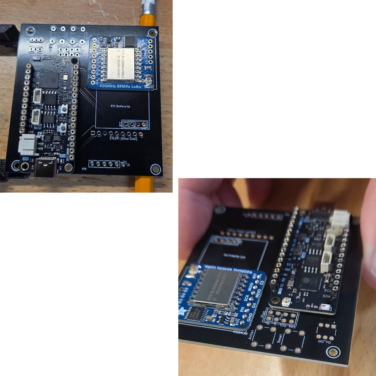
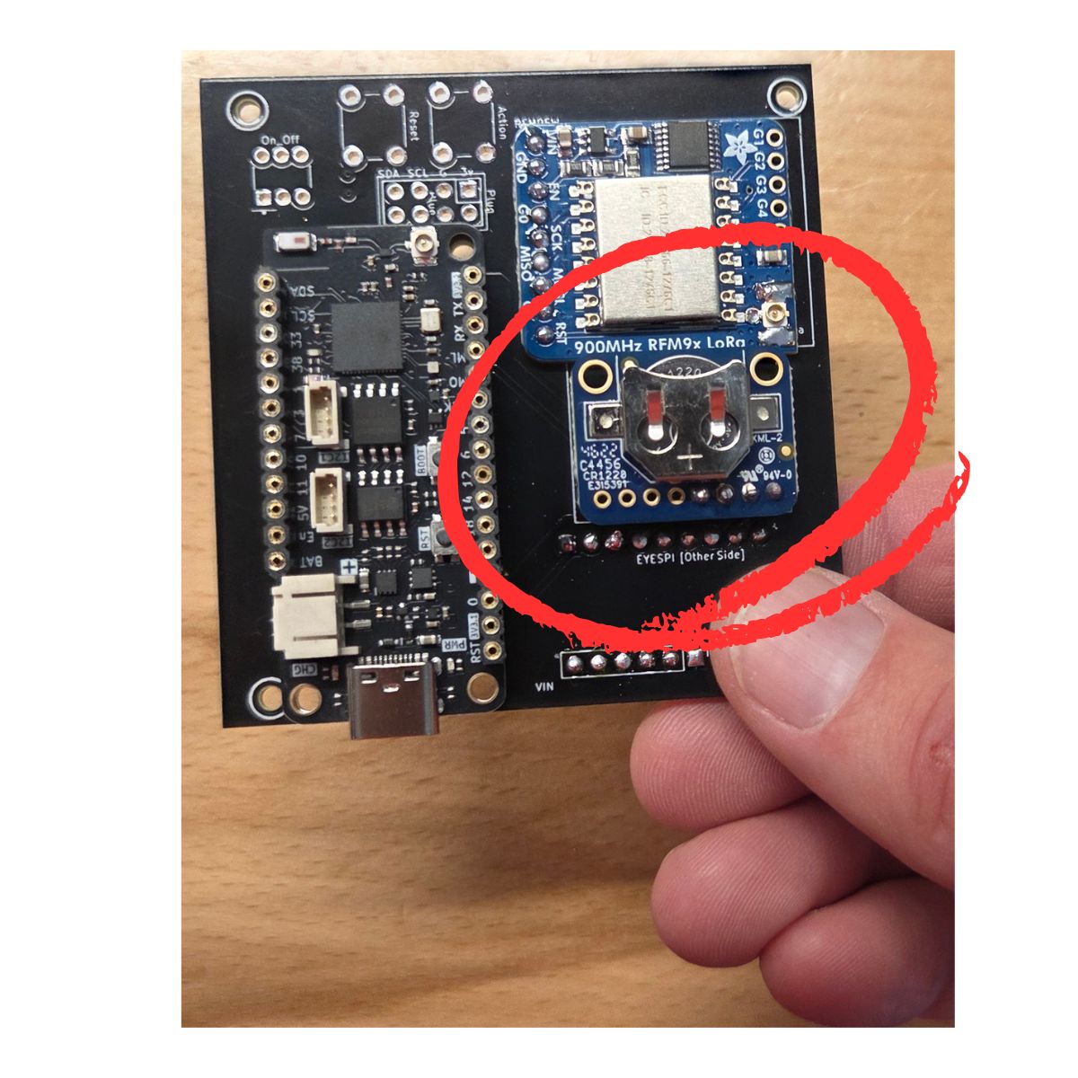
Place & Solder the RFM9x on Top of PCB
- Trim some standard header pins to the proper number of pins
- Place the RFM9x onto the PCB, with the pins in place
- Use some sort of spacer under the PCB so the pins barely protrude. Here you can see I use pencils
- Solder the tops of those pins into place
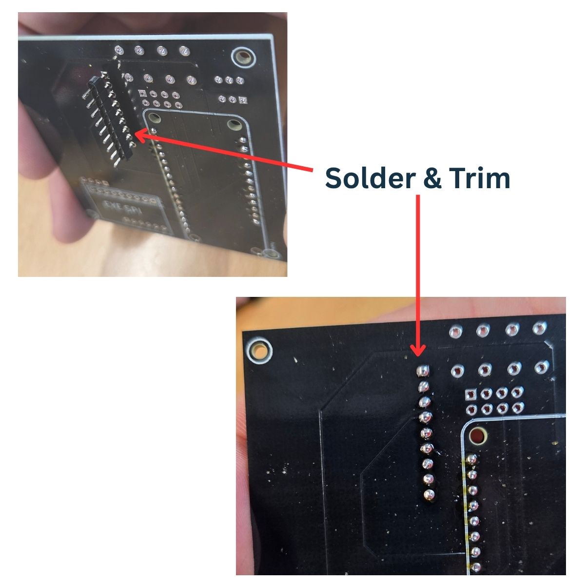
Trim & Solder the Bottom Pins
- At this point, the header pins will be protruding from the bottom of the PCB quite a bit, as shown in the image.
- Carefully trim these, close to flush with the PCB.
- Solder the pin bottoms into place.
- Make sure all pins have plenty of solder and no shorts.
Add EYESPI to the PCB
Place EYESPI Board onto the PCB
- Trim 2 standard pin header strips to lengths of 9 and 6 pins
- Place the EYESPI board onto the pin as shown, with pins in place
- Be careful to face it the correct direction. The black portion of the ribbon connector shoud be facing the edge of the board, as shown
Solder Pin Tops
- Solder the pin tops into place
- Use plenty of solder
Trim & Solder the Pin Bottoms
- Pins will be protruding from the bottom of the board
- Trim them nearly flush with the board
- Solder the pin bottoms into place
- Use plenty of solder
Add Realtime Clock
Solder RTC onto the Board
- Only 4 pins are connected for this
- Use standard header pins
- Solder the pin tops and bottoms, as with the other steps
Add a CR1220 Battery
- Go ahead and install the RTC battery now
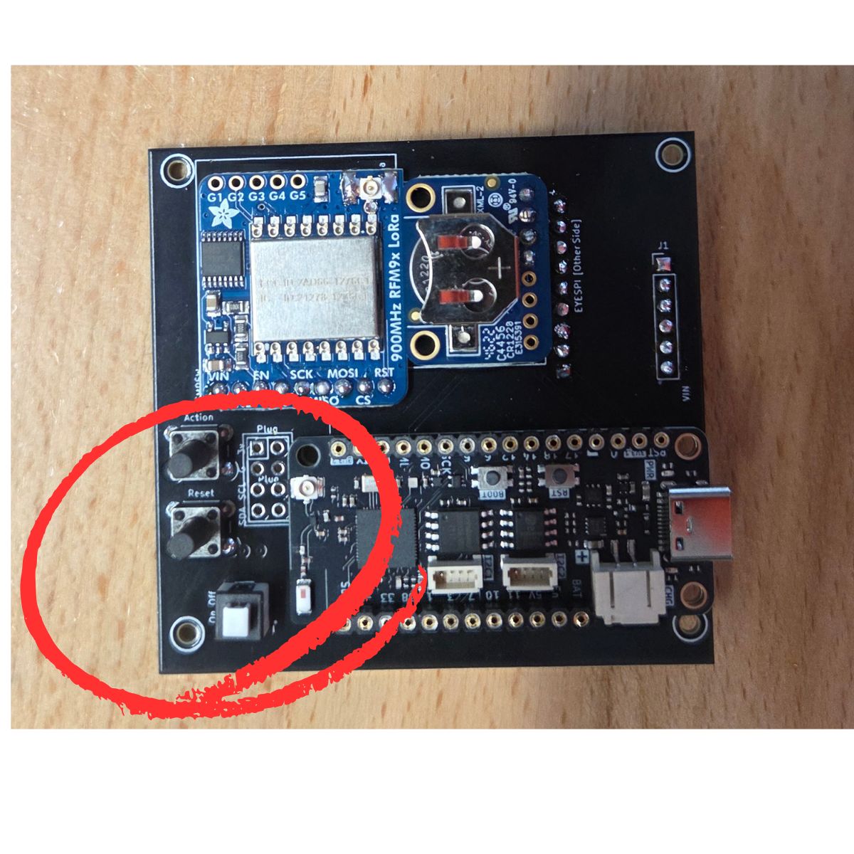
Place & Solder Buttons
- Place the 2 buttons and the on/off switch as shown
- Solder them into place from underneath the PCB
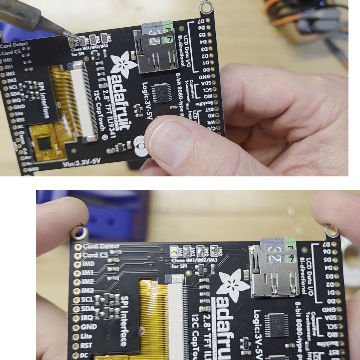
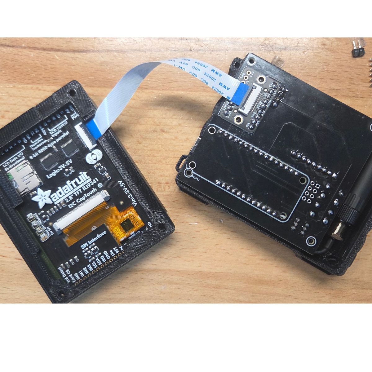
Switch the Display to SPI Mode
Connect the PCB and Display
- Use the ribbon connector as shown
- The black portion of each connector flips up to allow you to plug in the ribbon, then flips down to lock into place
- The blue portion of the cable should be facing away from the connector, as shown
SD Card Recommended
SD cards are not strictly required, but if you don't use one, you can't ever transfer your data to a different Blackout Comms device. If you do use an SD card, you'll be able to swap the SD card from this device to another with no trouble, and all your data will still be available. All sensitive data on the SD card is encrypted.
Card Compatibility
We highly recommend selecting a known-compatible SD card for use in your device, if you're using SD cards. Much of the hardware used by Blackout Comms is very picky about SD cards, and won't work with most > 32 GB cards. If you attempt to initialize your device and it becomes stuck (for more than 20-30 seconds) on the mounting SD step, it's likely your SD card is not compatible.
Known-Compatible SD Card List
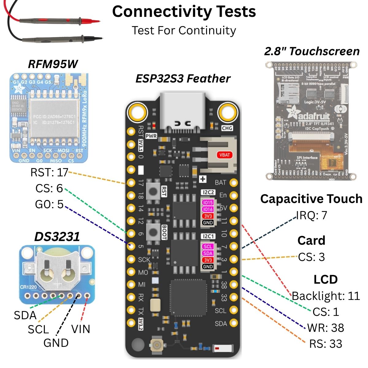
Test Connectivity Between Components (continuity)
Tests to Perform
- Use a multimeter to test for proper connectivity between the feather and the component pins listed in the graphic below
- Additionally, check all adjacent pins you soldered to make sure there is not continuity between neighboring pins (a short)
- If you power on the board before running these tests, you may "smoke" your board, or worse
- If there's any connectivity issue at this point, it's much easier to fix it now (takes a few seconds) rather than later when everything's put together
First Power On
- If all the tests passed, connect the board to power via the USB port, and power it on (power switch)
- The screen should power on and be white
- LEDs on the feather should light up
- If the screen does not light up white, double-check the ribbon connector and all pins
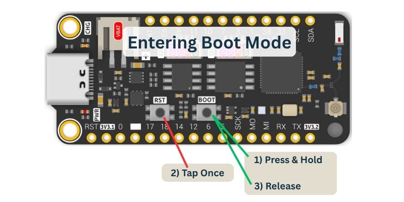
Flash the Firmware
Flashing The Device
The Blackout Comms firmware needs to be "flashed" (installed) onto the Pager. The basic steps are...
- Connect the device to your computer using a high quality USB data cable.
- Power-On the Pager
- Hold the boot button of the feather, tap the reset button (closest to the edge), and then release the boot button.
- Using Chrome or Brave (other browsers may work), go to the Altware Pager Firmware page.
- Click the install button
Restart Pager
At this point, with the firmware flashed and screen connected, the pager should show the Blackout Comms startup screen. If it does not...
- Double-check that you switched the TFT display to SPI mode (check a few steps above)
- Double-check continuity of all components
3D Print Your Enclosure
- Choose either 3MF or STL, depending on your print software
- You will need to print a case back, mid, front, and possibly a backpack cover (depending on options you select during the build)
- Any printable material is OK, but we've had good success with PETG.
- 3D print files are attached to this project and also available on Printables
Final Assembly - Putting it All Together
If you want to see the listed steps, check the DIY build guide, but here's a video walkthrough of it...