Create custom components for your projects using the PCB design software Autodesk EAGLE.
It can be difficult to find the right component you need for a project.
You can either use a different part and hope the component will fit, or alternatively, you can create a custom library in the PCB design software, Autodesk EAGLE and easily use the custom part in designs.
If you're unfamiliar with the EAGLE software, learn more about it in our Easier PCB Design: EAGLE CAD Tips and Tricks article.
Determine Component Measurements
The first step is to determine the exact measurements of the component you'll be using in a design.
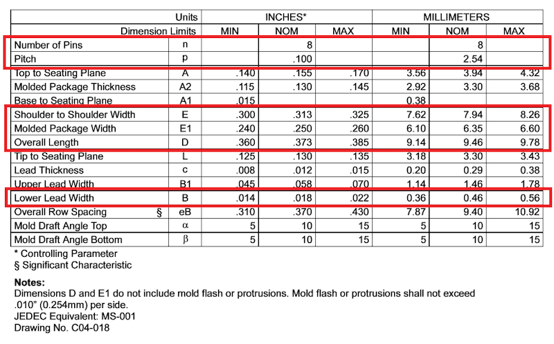
You can typically find sizing details in datasheets, along with part technical drawings and a table with dimensions listed.
Example of the sizing details of a component in a datasheet. Image courtesy of Microchip.
Don't worry if you can't find all the measurements. Just focus on the overall dimensions and the number, size and pitch of component pins.
Example of measurement table on a component datasheet. Image courtesy of Microchip.
Creating a Custom Library in the Autodesk EAGLE Software Application
Devices are often organized individually within packages using symbols, which are used in schematics or footprints and represent a physical component that can be used in PCB design.
To organize our custom part in the Autodesk EAGLE application, we'll start by selecting 'New' under the 'File' menu, then 'Library' to open up a new window.
A library window in the Autodesk EAGLE software with the 'Symbol' column selected.
Next, choose 'Add Symbol..." and name the file. It's recommended to follow the titling format: "SYM_devicename."
A new window will be prompted to open.
An example of the window that will appear once a new symbol is created in Autodesk EAGLE software application.
Drawing the Symbol
To draw the symbol, start by defining the component's outline. You can do this either manually or entering the coordinates of a rectangle within the command line.
Regardless of the method you use, select the line tool and make sure that 'layer 94' is selected and that your grid is properly configured.
Image highlighting location of layer 94, grid configuration button and the line tool in Autodesk EAGLE software application.
A simple outline of a box drawn in the Autodesk EAGLE software application.
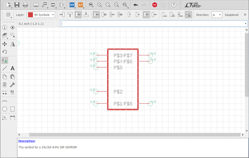
You can then use the pin tool to define the component input and output values. The green circles that appear will indicate where other parts connect to your symbol.
An example of how component input and output values should look on a grid in the Autodesk EAGLE software application.
This will only be used in a schematic, so feel free to place the pins in any order and position you prefer. It's recommended that the pin names be changed to fit the ones in your datasheet by using the info tool.
Example of how pins can be configured in the Autodesk EAGLE application.
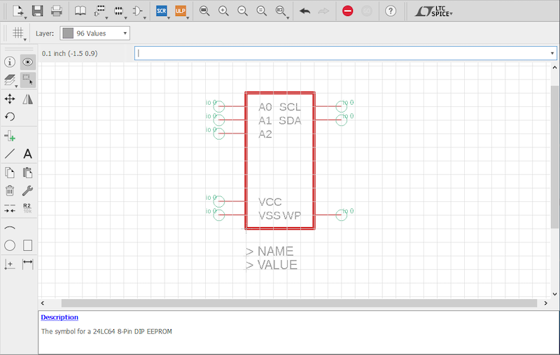
After you've finished, add two labels for the part name and value.
Then, use the text tool and make sure to place them on the correct layers (95 and 96).
Example of labeling a part name and value in the Autodesk EAGLE software application.
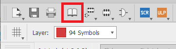
Save the drawing and return to the library window by clicking on the icon shown in the image below.
Image highlighting the location of the button which returns the user to library window in Autodesk EAGLE software application.
Creating the Footprint
The footprint is primarily used when designing PCBs and must be precisely drawn according to a component's datasheet measurements.
Start by defining the outline, just like before, but make sure to use the exact measurements. Tip: For added precision, use the command line to enter the point coordinates.
An outline of the specific measurements of a component drawn in the Autodesk EAGLE software platform.
For reference, take a look at the measurements entered for an example component used in this project listed below.
LINE
LAYER 21
(0 0)
(9.46 6.35)
(0 0)
Add the holes for the pins (or pads if you have an SMD part). If needed, use the pad tool for through-hole components and the SMD tool for SMD parts.
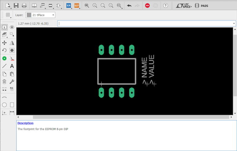
Example of a component footprint in Autodesk EAGLE software application.
The option bar, which appears above the command line after selecting the tool, allows the user to configure the hole diameter as well as other settings.
After placing the component pads, title them by using the info tool again. This step isn't necessary, but it will make things easier later on.
Note: You can also add text to your design.
Example of adding text to a component footprint in Autodesk EAGLE software application.
When satisfied with the footprint, go ahead and save it and return to the library editor.
Finish the Design by Linking Drawings
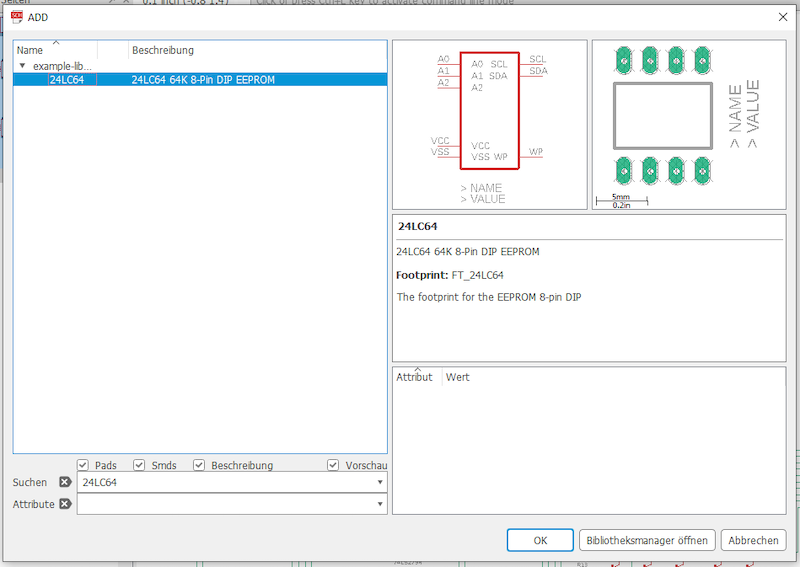
Once in the library editor feature, click "Add Device..." and name it. Now select the "Add part" button in window that opens up.
Image displaying the location of the "Add Part" and "Add Device" buttons in Autodesk EAGLE software application.
Select the symbol created earlier in this tutorial and place it anywhere in the main panel area. Then select 'New' and 'Add Local Package' on the right side of the window.
Image displaying location of the 'New' and 'Add Local Package' selections in Autodesk EAGLE software application.
Select the footprint you want to link to this symbol, which will be the one you created.
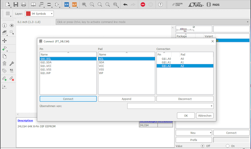
Click on the 'Connect' button to bring up a dialogue box, which allows the user to link the footprint pads and symbol pins together.
Image showing how to link component footprint pins and pads together in the dialogue box.
Click on 'Ok' button to close the dialogue window. Then save your work using in the Autodesk EAGLE application and close the library.
Inserting Component in a Design
To access your custom part, navigate to libraries, then 'Library Manager' from the main menu bar.
Image displaying Library Manager window in Autodesk software application.
Select your newly created library under the 'Available' tab and click the 'Use' button.
If the part happens to be loaded already, it will be stored automatically in the 'in use' tab instead.
After activating the library you can then use the part in a design.
Image displaying a stored component footprint in the Autodesk EAGLE software application.