Learn about different power sources and how to build a power supply for your electronics workbench!
An electronics workshop or workbench is essential for anyone who wants to be involved in electronics. It provides a place for different tools to be mounted and operate at the same time, it keeps all your parts in one place, and it helps to prevent cluttering up other spaces such as the bedroom, dining room, kitchen, and other people’s bedrooms.
Building a functional workbench can be a huge expense even when it doesn't need to be. In this series, I'll introduce you to important tools you should include on your workbench and show you how to build these tools. All electronic projects rely on a power source and so in this first project of the series, we are going to look at different types of power sources and build one of our own!
To Mains or Not To Mains?
One of the most readily available sources of power comes from the electrical grid—nearly all houses have power sockets used to power computers, TVs, kettles, vacuum cleaners, and much more.
While mains power is plentiful it is also very dangerous and it is shocking (pun intended) that so many retailers have hobbyists build AC-DC power supplies in kit form (please never do this, ever). Unless you are experienced in good electrical practice and safety then mains electricity is something that you should never directly tap into without a power adapter!
Power adapters (also called wall warts) are mains-powered devices that often provide a range of output DC voltages. These are an incredibly useful power source because:
- they can provide tens of watts of power;
- they are powered by the mains making them incredibly reliable;
- they use a transformer which isolates you and your project from dangerous voltages.
However, power adapters will often need some kind of regulation and smoothing to be used in projects, so they're best used with a power control circuit which is then connected to your electronic projects.
Batteries as a Power Source
Batteries are a very handy source of power for a number of reasons. First, batteries are widely available in a variety of packages and can be made to fit into just about any project. Second, they are widely available in shops, making them easily replaceable. Third, their outputs are perfectly smooth and require little to no decoupling.
But batteries are not a permanent source of power. They eventually “run out of juice” so they are not ideal for high-power projects (which would include the use of relays, solenoids, motors, high-power LEDs, etc).
Utilizing Negative Voltage Generators in Power Sources
Nearly all sources of power produce a voltage that has a positive (+) and a negative (–) terminal. Typically, the negative terminal is grounded and used as the 0V reference, meaning that the positive terminal will have a positive voltage (greater than 0) with respect to the negative terminal. This type of power supply is often referred to as a single rail supply and provides 0V and +V.
Most beginner projects only use a single rail supply, so batteries and wall warts make good power sources. Eventually, however, projects start to use complex op-amp circuits that require split rail supplies that require both a positive and negative voltage. For example, a 9V battery can be made to supply either 9V or –9V but it cannot do both.
If two 9V batteries are connected in series where the middle connection is used as ground (or 0V), then one battery can provide +9V while the other battery provides -9V. But using two power supplies like this is not often practical so this is where a negative voltage generator comes in!
A negative voltage generator takes a single rail supply and produces a negative voltage that is close to the supply voltage (for example, a 10V source connected to a negative voltage generator could generate -9V). How they work depends on the specific circuit but the circuit used in this project takes advantage of a special phenomenon called “capacitive coupling”.
Essentially, capacitors like to try and keep the potential difference across them the same at all times and a sudden change in voltage on one plate will result in the other plate following the same trend. For example, if the potential difference across a capacitor is 5V and one plate is forced to 10V then the other plate will rise by 5V (the difference). The same is true if the voltage across the capacitor is 5V and the 5V plate is rapidly pulled down to 0V then the other plate will reduce by 5V which will result in that plate being -5V. With some clever diode work, a simple negative voltage generator can be made using two capacitors, two diodes, and a 555 astable square wave generator!
Building a Power Supply
One of the main advantages of building your own power supply is the ridiculous cost savings and our power supply will have a number of features, including:
- Dual rail variable supply (both positive and negative voltages)
- Multiple fixed power outputs (3.3V, 5V)
- Powered via batteries or wall wart!
- Easily buildable on breadboard or stripboard
- Multiple displays showing various voltage levels
Power regulation can be done with one of two main methods: linear regulation or switch mode regulation. Switch mode regulation offers high efficiencies and low power dissipations, but they also require modules that are somewhat hard to use. Linear regulators are far less efficient, but they are also easier to implement and provide smoother power rails.
Therefore, we will use simple linear regulators in this project. Linear regulators such as the 7805 can offer up to 1A of output current while the LM1117 offers up to 800mA of current. Despite their lower efficiencies, linear regulator energy losses are proportional to the current draw so for most projects the energy losses will be negligible (and can be ignored if using a wall wart as a power source). If you plan to use batteries to power the supply, keep in mind that they could run out sooner than you may think!
Power Supply Schematic
The schematic for our power supply is incredibly simple and consists of:
- Input protection: used to protect our power supply and circuits connected to it
- Power switcher: allows us to either use batteries or a wall wart
- Variable dual rail supply: provides a variable output voltage (both + and – rails)
- Fixed supplies: provide the two most common voltage rails; 5V and 3.3V
Construction of the Power Supply
The power supply shown below was built using a mix of wood and 3D printed parts. Originally, I intended to build the front face using wood and machining but it turned out that designing and printing a 3D model was much easier (mainly due to the lack of need for machining).
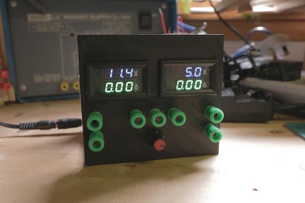
For the sake of demonstration, this power supply is not enclosed fully which shows the internal construction. 4mm banana plugs with screws are used as connectors to external circuits. The two displays on the front panel display the input voltage to the power supply and the voltage of the variable output respectively. More displays could be added to show the 5V and 3.3.V voltages but since these are fixed it is somewhat pointless.
The input voltage voltmeter also has an ammeter placed in series with the input power. This shows the current consumption of the system as a whole.
The constructed power supply (front view)
The constructed power supply (top view)
The constructed power supply turned on