In this article, learn how to use the AVR IDE to create projects, build basic circuits, and program your circuits!
AVR microcontrollers have some advantages over other similar micros, including higher MIPS and a friendlier architecture. In this article we will learn how to use the AVR IDE, create an executable project, build a basic AVR circuit, and then program it!
Schematic
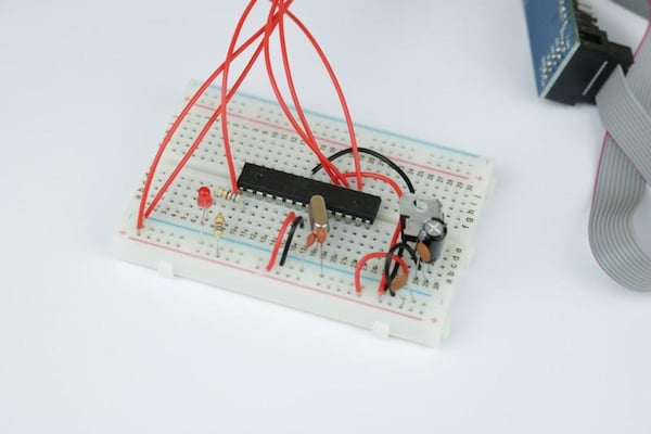
How to Build the Circuit
Building the circuit is rather easy and can be done using most circuit construction techniques including breadboard, stripboard, veroboard, and PCB.
The schematic in this project shows the use of a simple power regulator circuit (using the 7805) that provides the ATMEGA device with 5V, but it turns out that the USBASP programmer provides approximately 3.3V. Despite this, it is better to provide external power to prevent the USBASP from drawing too much current from any USB port.
The USBASP programmer I purchased also came with a converter that converts the 10-pin program header to a more convenient 6-pin program header. Still, the header uses a two-row 2.54mm pitch spacing, which means it cannot be connected to a breadboard. To get around this, I simply connected the header to wires that connect to the various programming pins on the breadboard.
How to Install AVR Studio
AVR devices are programmed using a specially modified Visual Studio 2015 called AVR Studio 7, which can be found on the AVR website. The first step in programming AVR devices is to download the web installer (a small application that downloads the needed files) and then once downloaded, run the installer.
The first option that you will be asked is about license agreements and sending anonymous information; I personally recommend that you do not send anonymous data for a number of reasons (due to extreme paranoia).
The initial installer page.
The next page asks which architecture you want to install. Since this range of tutorials will only be covering devices from the AVR 8-bit MCU range, this will be the only selected option. However, if you have a decent download speed (mine is only 4mbps), then selecting all options could be beneficial for the future.
With the device support selection done, the next page asks about the Atmel Software Framework and example projects. For now, ensure that this is checked.
The next page simply checks your computer to see if there will be any potential problems such as a pending restart (due to an update), or if the system will not be able to run the IDE. If all are checked, click “Next”.
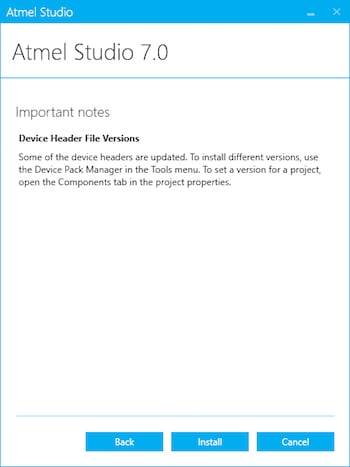
If you have already installed an earlier version of AVR IDE, you may get the following window. If so, just click “Install”.
Now it is all about patience, waiting for the IDE to download all the needed components and install.
Once done, you will be prompted with the option to launch Atmel Studio 7.0. Ensure this is checked before closing the installation window.
How to Install WINAVR
While Atmel Studio 7 is useful for writing code, it is not the best when it comes to programming AVR devices using open-source tools. Therefore, to make this easier in the compilation/programming stage, we will use WINAVR, which also comes with AVRDUDE to upload our code into the Atmega device. To download WINAVR for Windows, simply click this link and select the exe file.
Once downloaded, run the installer and go through the various options until it asks for an install destination.
The best place to install WINAVR is the given recommended location of C:\WinAVR-20100110. The next option will ask about PATH environments, and you must make sure that all the checkboxes (shown below) are checked.
Once the install button is clicked, the installer will do the rest of the work, and once done, the installer will close.
How to Connect USBASP and Install Driver for Windows
If you are using Windows, you will need to change the USB driver for the USBASP. This is done easily with a tool called Zadig. Simply put, download Zadig (download link), connect your USBASP device to your PC, wait for Windows to automatically install USBASP, run Zadig, locate the USBASP device on the drop down list, and then select the driver “libusb-win32 (v1.2.6.0)”.
Once you click “Replace Driver” (or Reinstall Driver), Zadig will automatically install the driver needed to get USBASP to work on Windows.
How to Configure Atmel Studio 7 and WinAVR
Atmel Studio 7 will not natively use WINAVR or AVRDUDE, so we have to configure it to do so. This may seem daunting, but do not panic; only one instruction line is needed for AVRDUDE to program the device, and only one directory needs defining. In fact, you should be able to copy and paste the code in this article for any ATMEGA168-based project!
So, the first step is to tell Atmel Studio 7 what compiler it should use. To do this, open Atmel Studio 7 (if it is not already open), and click Tools > Options.
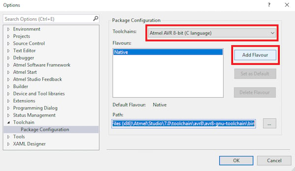
In the window that opens, use the list on the left to navigate to Toolchain > Package Configuration and in the options that should now be available on the right, select Atmel AVR 8-bit (C language) from the drop-down box and then click “Add Flavour” (or "Flavor" for you in the US).
Assuming that you installed WINAVR in its default location (in the C drive) and that you have the same version as WINAVR as in this article, the window that pops up can be filled in as shown below. Once filled, click “Add”, and when you return to the previous window, click “OK”.
Atmel Studio 7 can now use WINAVR to compile your AVR programs, but it still cannot program the devices. To do this, we need to add an external tool to Atmel Studio 7 and configure it for the ATMEGA168 device.
The first step is to navigate to Tools > External tools. The window that opens up is the only window that is needed to get the USBASP programmer to work. The window below shows most of the details you will need to fill in.
The arguments box does not fully show all the information that is needed, and so below is what was filled in.
avrdude -c usbasp -p atmega168 -U lfuse:w:0x26:m -U flash:w:$(ProjectDir)Debug\$(TargetName).hex:i
Most of the information in this argument is not important to you, but there are two pieces of text that are. The first one is -p atmega168; this tells AVRDUDE that we are programming an ATMEGA168. If your project uses a different chip, replace the atmega168 text with the device you are using (such as the atmega88).
The second parameter is -U lfuse:w:0x26:m, which is specific to the ATMEGA168. This instruction tells the AVRDUDE to configure the device to use an external crystal, and once programmed, the device will only run when connected to a crystal circuit (see the schematic).
Note that this also means that the device requires a crystal when being programmed.
This argument will only work for the ATMEGA168! If you try to use it for other devices, you may brick those devices and thus waste ICs! To keep things simple, get yourself an ATMEGA168.
Creating Your First Project
The next task is to create an AVR project and test out the circuit, compiler, and programmer.
First, navigate to File > New > Project, and in the window that opens, select “GCC C Executable Project” and in the name text box call the project whatever you like.
The next window that should appear is the device selection window. From this list, select the Atmega168. To my knowledge, this window is pointless since we pass the device name to AVRDUDE manually anyway (so far I cannot find a method to make Atmel Studio 7 automatically send the device name to AVRDUDE via arguments).
The result should be a main.c file that contains our program code that the AVR will run. However, the generated code does nothing, so replace all of the contents of main.c with the program below (make sure to save the file once the new code has been entered).
Now it’s time to compile the code and upload it to the AVR device.
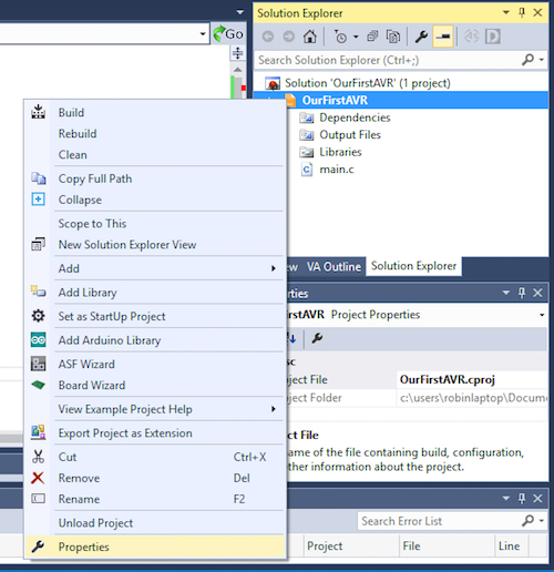
The first step is to ensure that our project is using the WINAVR compiler. Right-click the project in the solution window and navigate to “Advanced” in the properties window. In the “Advanced” window, ensure that WINAVR is selected in the Toolchain Flavour box.
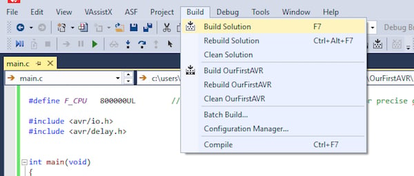
Save the project and compile it by clicking Build > Build Solution (or pressing F7).
If all goes to plan, the following message should appear in the output window:
Build succeeded.
========== Build: 1 succeeded or up-to-date, 0 failed, 0 skipped ==========
This means that our project has successfully compiled and is ready to be transferred to our chip.
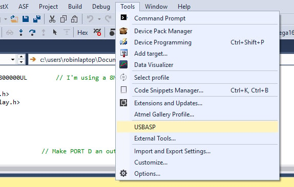
To program the device, ensure that the USBASP is connected to both the PC and the Atmega circuit, the circuit is powered, and that the chip has a crystal connected (in case the IC has been configured to use an external crystal).
Then, with all of this done, click Tools > USBASP, and from there everything should work automatically.
If all goes well, the LED on your circuit should start blinking! Below is the output from AVRDUDE in Atmel Studio 7 to show what a successful program looks like.
avrdude.exe: warning: cannot set sck period. please check for usbasp firmware update.
avrdude.exe: AVR device initialized and ready to accept instructions

Reading | ################################################## | 100% 0.01s

avrdude.exe: Device signature = 0x1e9406
avrdude.exe: NOTE: FLASH memory has been specified, an erase cycle will be performed
             To disable this feature, specify the -D option.
avrdude.exe: erasing chip
avrdude.exe: warning: cannot set sck period. please check for usbasp firmware update.
avrdude.exe: reading input file "0x26"
avrdude.exe: writing lfuse (1 bytes):

Writing | ################################################## | 100% 0.00s

avrdude.exe: 1 bytes of lfuse written
avrdude.exe: verifying lfuse memory against 0x26:
avrdude.exe: load data lfuse data from input file 0x26:
avrdude.exe: input file 0x26 contains 1 bytes
avrdude.exe: reading on-chip lfuse data:

Reading | ################################################## | 100% 0.00s

avrdude.exe: verifying ...
avrdude.exe: 1 bytes of lfuse verified
avrdude.exe: reading input file "c:\users\robinlaptop\Documents\Atmel Studio\7.0\OurFirstAVR\OurFirstAVR\Debug\OurFirstAVR.hex"
avrdude.exe: writing flash (184 bytes):

Writing | ################################################## | 100% 0.11s

avrdude.exe: 184 bytes of flash written
avrdude.exe: verifying flash memory against c:\users\robinlaptop\Documents\Atmel Studio\7.0\OurFirstAVR\OurFirstAVR\Debug\OurFirstAVR.hex:
avrdude.exe: load data flash data from input file c:\users\robinlaptop\Documents\Atmel Studio\7.0\OurFirstAVR\OurFirstAVR\Debug\OurFirstAVR.hex:
avrdude.exe: input file c:\users\robinlaptop\Documents\Atmel Studio\7.0\OurFirstAVR\OurFirstAVR\Debug\OurFirstAVR.hex contains 184 bytes
avrdude.exe: reading on-chip flash data:

Reading | ################################################## | 100% 0.10s

avrdude.exe: verifying ...
avrdude.exe: 184 bytes of flash verified

avrdude.exe: safemode: Fuses OK

avrdude.exe done.  Thank you.
Conclusion
Starting with AVR devices can be somewhat tricky if you do not use an official programmer that can work out of the box with Atmel Studio 7. However, only one command line needs defining in the programming tool (device type, fuse, etc.) and all future projects can use the same tool/compiler which only needs to be configured once.
So the next ATMEGA168 project you do can use the same compiler and external tool as seen in this project and require no adjustments! Of course, more advanced projects may need to change fuse bits, but for now, this tutorial should get you going with AVR devices.