Learn all about ripples and how to filter them out from your power supplies for a more efficient circuit!
Most power supplies and power sources such as batteries provide an output with ripple. Ripple is a variation or an unnecessary frequency for components in DC voltage. Ripple can be negligible relative to the DC voltage or the DC component, or very high in the range of thousands of volts in cases of high voltage DC systems.
Ripple arises from the AC power where the DC voltage is derived and it may lead to undesirable effects in circuits. Batteries also supply ripple in their output. This ripple increases as the battery gets closer to dying. Knowing this, charging a battery needs to be done with ripple-less supply to maintain the battery's health.
Ripple can be considered a waste of power. Dissipation of this power can lead to heating of components, distortion due to variations and noise, and can cause complex digital circuits to work improperly. Thus, it is necessary to get rid of this ripple from your power source.
Using Filter Circuits to Remove Ripple
Ripple is not originated but is instead due to an incomplete suppression of AC power after rectification. In the process of conversion from AC to DC, the ripple voltage we get at the output is very large depending on the forward voltage of the rectifier diodes. For reducing ripple, filter circuits are generally used in complex circuits. A filter circuit removes the unwanted frequency components called ripple.
A filter allows certain desired frequencies to pass through while suppressing the unwanted ones. Filter circuits are not only used in DC power supplies. They’re also found in a variety of applications like audio electronics, ADCs, and more.
Before filtering, there's one more thing to worry about: reversal of polarities. Reversal of polarity leads to many unwanted problems, including malfunctions and smoke from circuits. It can do a good amount of damage to circuits. Also, connecting a battery with incorrect polarity is an easy mistake. Almost all circuits come with a reverse polarity protection circuit but if they don't, it is important to build one and add it while you power your projects. Luckily, it's a very task to build one of these circuits.
Solutions for Reducing Ripple
There are numerous solutions for eliminating or reducing the above-stated problems and we will discuss the most efficient ones here. First of all, for ripple rejection, we need a filter circuit. Before filtering, we need to understand the ripple from the rectifier.
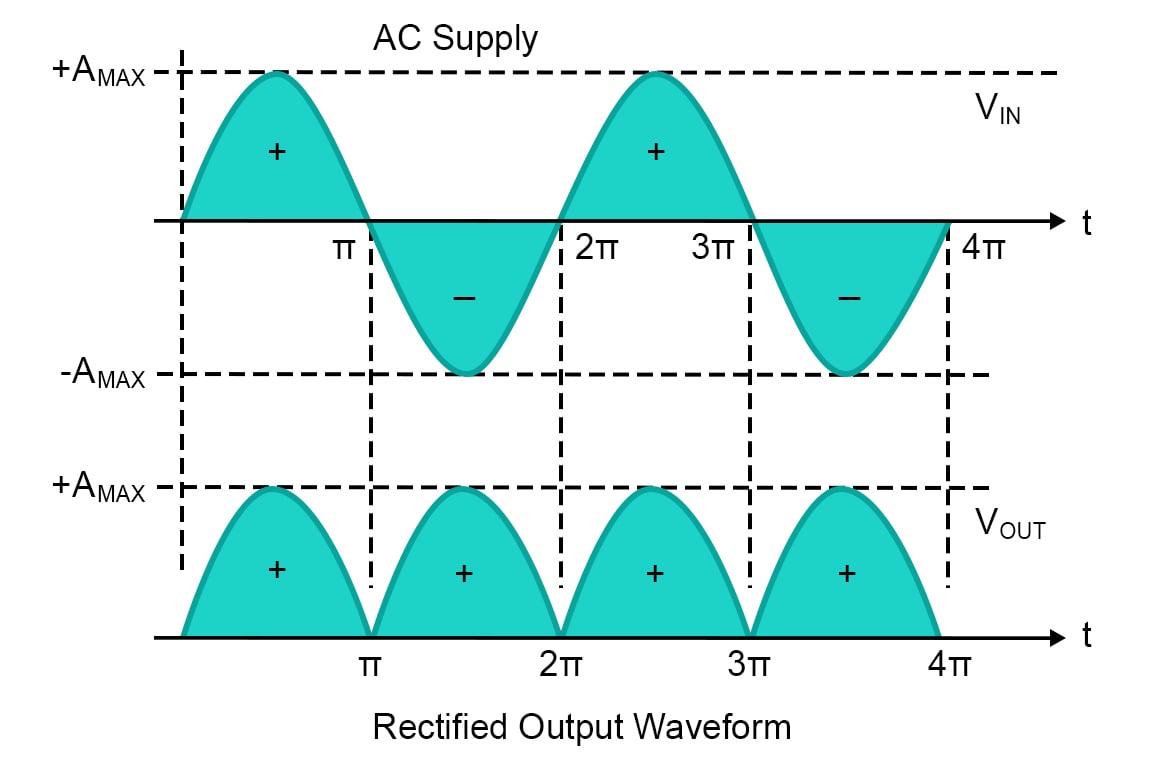
Selection of a rectifier type can also help us in ripple reduction as a single-phase half-wave rectifier consists of the highest ripple and reduces the full-wave rectifier. It will reduce further and become minimal in three-phase rectifiers.
Here are the waveforms of a half-wave rectifier and full-wave rectifier:
Input and output waveforms of a half-wave rectifier
Input and output waveforms of a full-wave rectifier
Filters can be made simply from passive elements: resistors (R), inductors (L) and capacitors (C). They can be made by a single energy storage element inductor or capacitor. A capacitor filter is a very widely used filter type in which the capacitor stores the unwanted DC components and provides load when needed thus stabilizing the system and providing a good amount of ripple rejection.
An inductor filter works the same way — it offers high impedance to the ripples and low impedance to DC components, thus ripple is reduced.
How to Utilize an LC Filter
LC filter is a very effective circuit to reduce the ripple made by two energy storage elements. It combines the smoothing action of both the inductor and capacitor making a perfect tool to reduce ripples.
These filters are used for applying analogue reference to MCUs as the analog reference voltage must be very stable to read the sensor values correctly. They are also used in radio communication, voltage magnifications, amplifiers, tuners, etc.
Types of LC Filters
There are two types of LC filters categorized for changes in the arrangement of inductor and capacitor:
- Inductor input filter
- Capacitor input filter
Inductor Input Filter
This type of LC filter is very common. Here, the inductor allows the desired DC component to pass through and then this DC component is further stabilized by the shunt capacitor, thus greatly reducing ripple.
For more ripple rejection, the impedance of the inductor must be greater than the impedance of the capacitor at ripple frequency.
Capacitor Input Filter
In a capacitor input filter, the input is provided to the shunt capacitor and most of the filtering is done by it, with an inductor further smoothing out the DC component.
This filter is suitable for high voltage applications but has many disadvantages like poor voltage regulation and, more importantly, high peak inverse voltage.
Utilizing an RC filter
To eliminate the drawbacks of the capacitor input LC filter circuit, we replace the inductor with a resistor. The unwanted DC components drop across the resistor and so, many times, there is a large voltage drop across the resistor and it heats up. This may lead to poor voltage regulation. Therefore, this circuit can only be used in low power applications. There are two types of filters based on the arrangements of R and C:
- Low pass filter
- High pass filter
Note: You can cascade two or more filters if you want even more ripple rejection. For example, you can cascade two RC filters if you get undesired voltage from the first filter. However, keep the voltage drop across each filter in mind.
Solutions for Eliminating Ripple
Up to this point, the filters discussed can be used to reduce the ripple. To eliminate it altogether, we have to use a linear voltage regulator to dissipate unwanted frequency components in the form of heat providing very stable output.
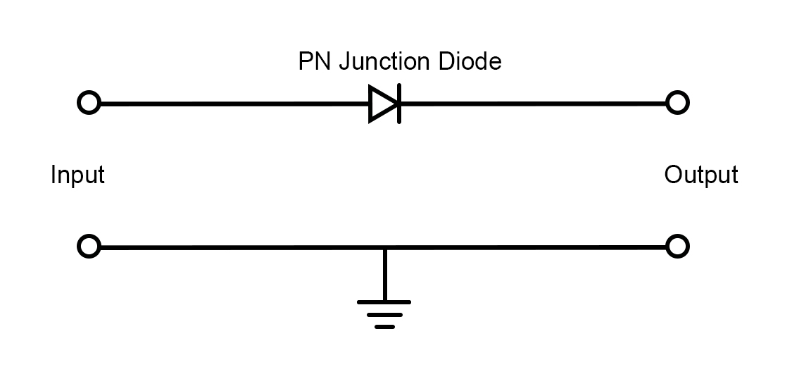
Let’s first talk about reverse polarity protection. The very obvious and simple solution to this problem is using a PN junction diode, which allows the circuit to work in correct polarities and for large currents. We can use diodes in parallel to share the load.
There are many drawbacks to this, one of which is a large diode drop. The diode drop of a PN junction diode is 0.7V which is large. This much power dissipation across the diode quickly heats it up at high power, making it an inefficient circuit for this task. However, we can use a Schottky diode to minimize this drop voltage and heating effects. The voltage drop across Schottky diodes can be less — closer to 0.1V- 0.2V — but these diodes can cause problems when designing an efficient system.
Another way to eliminate ripple is to use a bridge rectifier as it is regardless of polarity. However, note that the amount of power lost here would be twice as much as a PN junction diode.
A more efficient solution would be to use a P channel MOSFET. To make the pass transistor active, we have to apply a GATE pin to ground. Then, it makes a good fit for our application.
Reverse polarity protection circuit using a P-channel MOSFET
Utilizing a Relay for No Power Loss
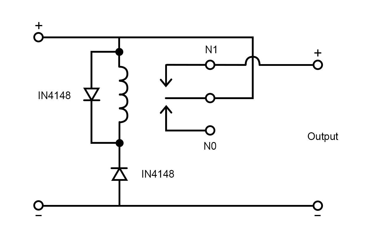
If you want absolutely no power loss, using a relay would be the perfect solution. We can connect the source supply with correct polarities and connect the load to the NC pin which powers the load with absolutely no loss at all. But when reverse polarity is connected, the relay activates, disconnecting the load from supply. This provides very efficient protection for reverse polarity.
Reverse polarity protection using a relay
Designing a Protection Circuit
Now, let's make a practical protection circuit combining a filter circuit and a reverse polarity protection circuit.
For the reverse polarity protection circuit, we choose the most efficient relay-based circuit. D1 protects from back EMF and prevents electrical noise, so a diode is always accompanied by a relay. D2 works in forward bias condition when reverse polarity is applied and thus the relay is activated. An LED2 is kept to give us the indication that reverse polarity is detected and load has been disconnected. LED1 is kept to indicate correct polarities and additional bypass capacitors are connected at the input.
Our filter circuit is made up of numerous energy storage elements: inductors and capacitors connected in such a combination that it can filter ripples and also provide less impedance.
To summarize our discussion, we first looked at the problems around ripple and reverse polarity and what effects they can have on our circuits. Then we discussed some solutions to eliminate or reduce these issues. Finally, we designed an efficient circuit that can be used to reduce ripple and protect our load from reverse polarity.