Learn about multi-stage battery chargers, how they're used, and the circuit diagrams needed to build one yourself.
Three-stage battery chargers are commonly referred to as smart chargers. They are high-quality chargers and are popular for charging lead-acid batteries. Ideally, however, all battery types should be charged with three-stage chargers. For the more expensive lead-acid battery, this three-stage charging process keeps the battery healthy.
Before getting into three-stage battery charger circuits, we must understand more about multi-stage battery chargers and why they are used.
What are Multi-stage Battery Chargers?
Multi-stage battery chargers sense the battery’s requirements and automatically switch to CC-CV mode, guaranteeing optimum efficiency and longer battery life. These battery charging technologies usually rely on microprocessors for anywhere from 2- to 5-stage regulated charging.
A two-stage battery charger has (obviously) two stages: bulk and float. You can observe these stages on a common mobile battery charger controller circuit. Here, the bulk stage is generally referred to as the boost stage in which the battery is charged at high currents for a short amount of time. The float stage which is also referred to as trickle charging happens when the battery is charged at a self-discharging rate.
Some chargers have a recovery stage for recovering flat batteries. As mentioned earlier, these chargers increase efficiency and provide a longer life to batteries. You might have seen people charging lead-acid (or other expensive) batteries with a constant power supply. Doing so is like giving a slow death to your batteries!
The Three-stage Charging Process
As the name states, there are three stages in this charger: bulk, absorption, and float. Let's discuss each stage.
Bulk Stage
About 80% of the battery is charged in the bulk stage. Here, a constant current of 25% of the Ah rating is provided. For example, in the case of 100Ah battery, 25A of constant current is fed and voltage increases with time.
You can increase the current to the battery more than 25% of its capacity, which will decrease the charging time but also may decrease battery life so it’s not recommended to apply a higher current than specified. Remember to check out the charging recommendations from manufacturers, some batteries also specify 10% of the capacity.
Absorption Stage
At the absorption stage, the remaining 20% of the battery is charged. Here, the charger feeds the constant current same as the absorption voltage of the charger, which depends on charging options and this current consumption decreases until the battery is fully charged.
Sometimes, however, the current does not drop as expected. In this case, the battery might have permanent sulfation. Permanent sulfation occurs when a battery has been in a low state of charge for weeks or more and restoration of the battery is then impossible.
Float Stage
In the float stage, the charger tries to maintain the fully charged battery in the same state indefinitely. Here, voltage is reduced and a current of less than 1% of the battery's capacity is applied. You can leave battery charging in this state forever and no harm occurs to the battery.
Three-stage Battery Charging Circuits
Let’s talk about a normal 12V, 7Ah battery. Its absorption voltage is 14.1V to 14.3V and float voltage is 13.6V to 13.8V. Knowing this, we need a circuit in which we can adjust the voltage over time, so it would be easier to control it with the help of a potentiometer or we can use a microcontroller of the task.
A LM317 voltage regulator IC is the first thing that comes to mind for these applications. You can select the LM338 or LM350 according to your current capacity requirements. We need some resistors at the adjust pin of the IC to control output voltage. For this, we use 5kΩ and 2kΩ potentiometers as we have a fixed 270Ω sink resistor.
An LM317-based battery charging circuit where a microcontroller is used for switching voltage levels.
In the above circuit, we disconnect the controller and set VR1 to read 14.1V at the point shown in the diagram, and then set VR1 to read 13.6V.
We have to adjust VR2 to get a 0.5V voltage difference at the specified point. Now we connect the controller output pin and when controller output is LOW, we get 14.1V at the output and when HIGH we get 13.6V at the output.
Diodes are kept for reverse current protection. We are using 0.2Ω, 5W resistor as a current limiting resistor.
Using a Controller to Control Voltage
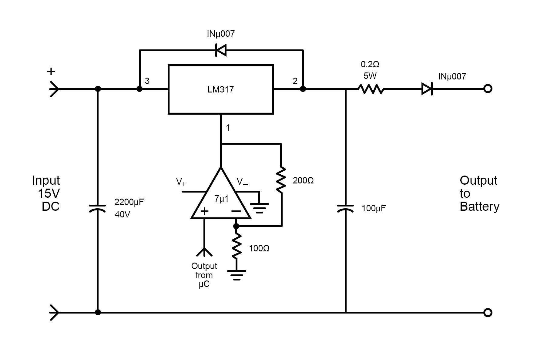
In the presented circuit, we use a microcontroller to switch the voltages. If we want to control voltage directly via a controller, we can by simply using a non-inverting amplifier made by a 741 op-amp.
We can scale a 0.5V input from the microcontroller to 0-15V. The gain of our amplifier is 3, so we can easily scale our microcontroller PWM voltages to 0-15V. Further, we can add a small capacitor to ground from a non-inverting pin.
A microcontroller PWM-based battery charging circuit.
You can also make an automatic charger while reading the voltage from batteries and switching accordingly. For this task, there is a great little IC out there: the LT3652 by Linear Technologies.
The LT3652 is a 1A solar-powered three-stage lead-acid charger IC — perfect for our application. It automatically falls to a 13.5V float charge mode when the charge current falls to 0.1A and it monitors battery continuously for efficient power management.
Circuit diagram for the LT3652 three-stage lead-acid charger IC. Image source: Analog Devices.
In this tutorial, we discussed three-stage battery chargers, their stages, and how they work. We finished by discussing different circuits to use if you want to make your own 12V three-stage battery charging circuit.