Having issues with digital circuits? This article on Karnaugh Maps will help you simplify complex logic functions!
In this article, I’ll discuss how you can use Karnaugh maps to simplify complex logic functions for implementation in a digital circuit. Note that this is only a summary of the topic and that there’s much more to cover. However, it should give you a good overview so that you can start designing simple digital circuits right away.
To keep this article short, I’ll assume that you already know how to count in binary and how you can convert decimal numbers to binary values and vice versa. If you need a refresher, check out Decimal Versus Binary Numeration which more thoroughly covers the topics.
An Overview of Logic Gates
The simplest logic functions are NOT, AND, and OR. You can derive any other logic function by combining the NOT function with either AND or OR.
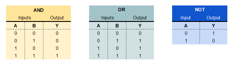
A logic gate that implements the AND function outputs a HIGH state if and only if all inputs are HIGH at the same time. An OR gate outputs a binary 1 if at least of its inputs is HIGH. A NOT gate outputs a binary 1 if the input is LOW and vice versa.
Outputs of NOT, AND, and OR logic functions.
Reading and Creating Truth Tables
In the truth tables above, every input has its own column and every possible combination of input values is represented. The output is always stated for a combination of input signals. To create a truth table, start by writing down all the possible input combinations. Next, determine how you want your output(s) to behave for each pattern.
Truth Table Example
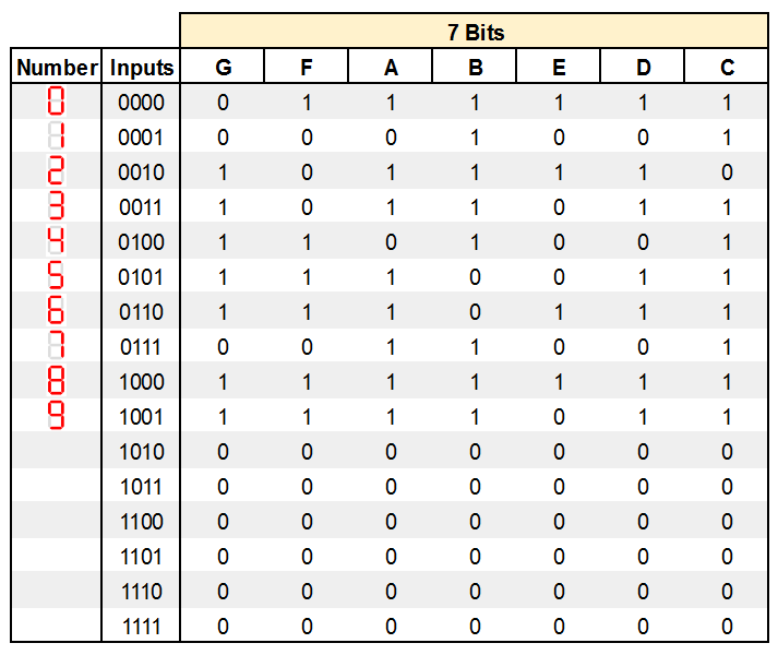
I want to build a digital circuit that can output a single decimal number on a seven-segment display. To accomplish this, we first have to determine which segments need to be turned on for every number. Knowing this, I created the following truth table.
My completed truth table helps determine which segments need to be turned on for every number.
Now, if we inspect G, we can see which input combinations the output has to have enabled (the dash in the center of the seven-segment display).
Once you created a truth table, you have to come up with a logic formula that represents the output function. The easiest way to do this is to fill out a Karnaugh map.
How to Create Karnaugh Maps
In a Karnaugh map, each cell represents one combination of input values, while each cell’s value represents the corresponding binary state of the output.
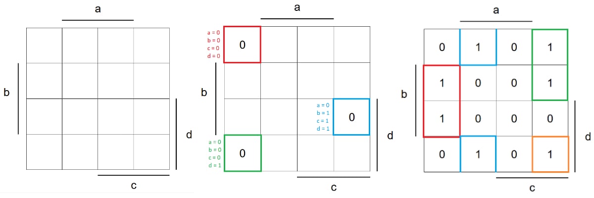
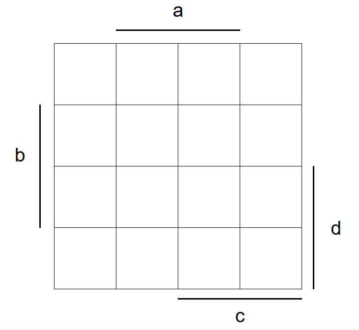
In this example, we have four inputs, and the K-map consists of four rows and four columns where the inputs are aligned, as seen in the image below.
Note: The Karnaugh map will be different if you change the number of inputs.
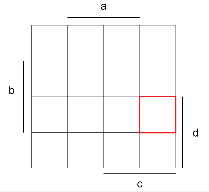
Our basic Karnaugh map template.
The 16 fields in the map correspond to the 16 different combinations of the four input signals (a-d) in the truth-table. As you can see, some columns and rows are labeled with letters. In those rows and columns, the corresponding input-variable has a value of one. Otherwise, this variable has a value of zero.
Therefore, the input 0111 (a = 0, b = 1, c = 1, d = 1) is represented by this cell in the map:
Input 0111 (a = 0, b = 1, c = 1, d = 1) is represented by the cell highlighted in the map.
Now we need to fill in the value of the output for every possible input combination.
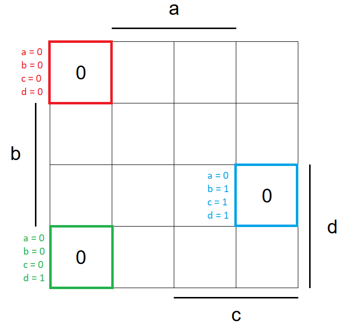
Let’s start with the ones where G is zero. Note, that this is the case when all inputs are LOW in the truth-table above. The other two valid cases where the result is zero, are 0001 and 0111 (shown below).
Determining all cases where G=0.
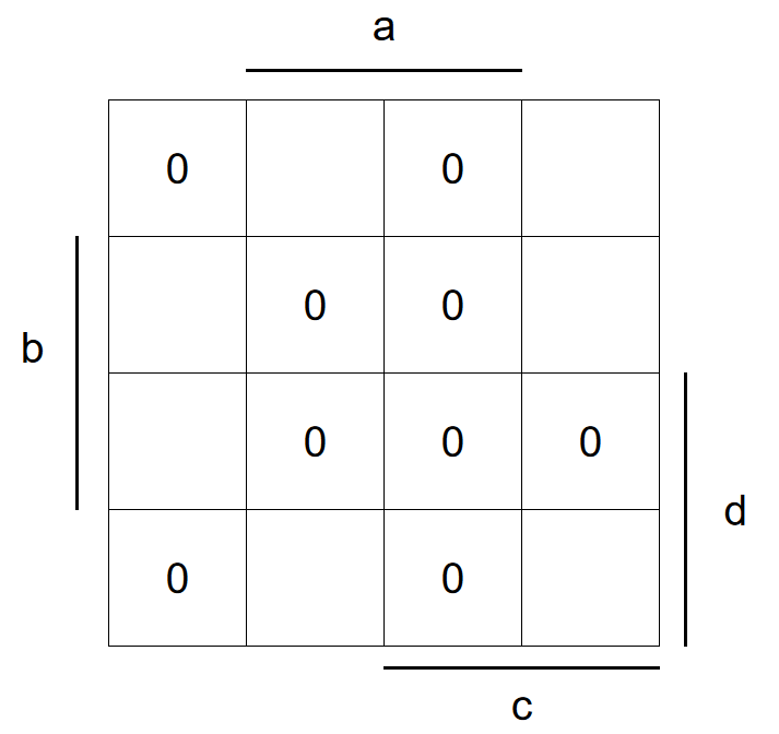
Next, I’ll cover all the invalid states. Those are all of the inputs that don’t represent a single-digit decimal number. If the inputs represent an invalid state, each segment should be turned off.
All invalid states will equal 0.
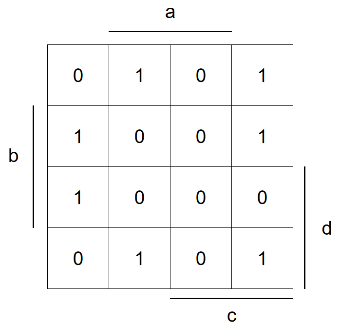
In all of the remaining cases, G has a value of one making it easy to complete the matrix.
The remainder of the cells where G=1 completes the Karnaugh map.
Deriving an Output Formula
To determine a simplified output formula, we have to find groups of adjacent cells that have the same value. These groups must have an area that is a power of two (one, two, four, eight, and so on), and we don’t have to stop at the borders of the matrix.
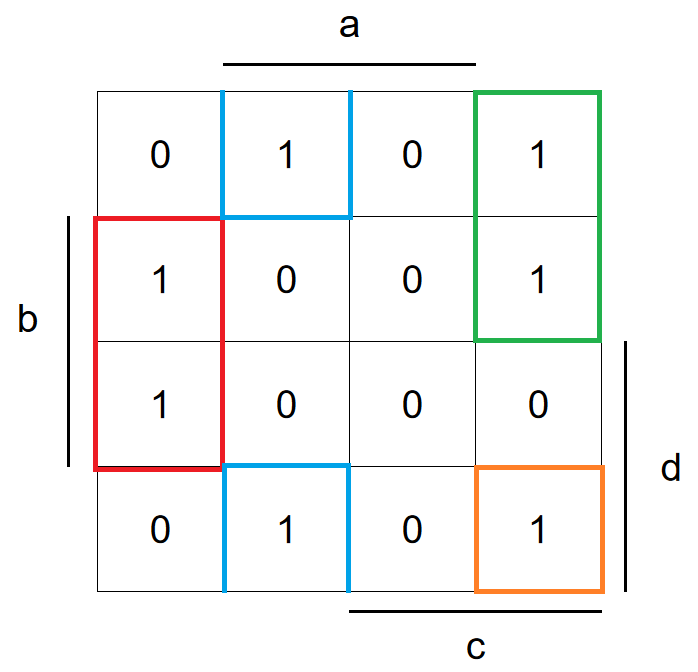
So in this map, I could find the following groups on ones (we could also group zeros but I won’t discuss that approach here):
As you can see, the blue group wraps over to the other side of the matrix, to form a larger area instead of two smaller ones. In general, we should try to form the largest possible group, which will result in a simpler function at the end. Note that diagonal groups are not allowed.
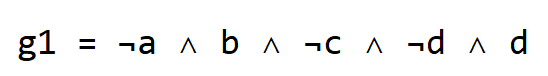
To derive the formula, look at each group's position in the matrix individually. The red group, for example, is situated in the fields (NOT a) and (b) and (NOT d) and (d) and (NOT c), which is described by the following formula:
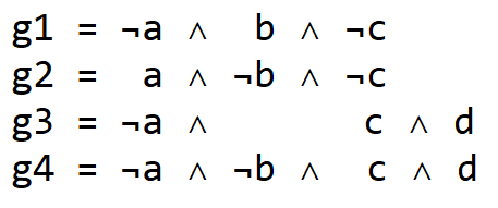
We can simplify this formula by removing (NOT d) and d. Now, repeat this process for all of the other groups. We should end up with these four (already simplified) expressions:
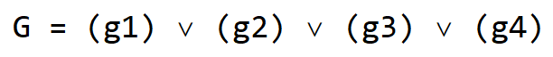
Once we have those, we just need to connect them with OR expressions to get the final formula for the output G:
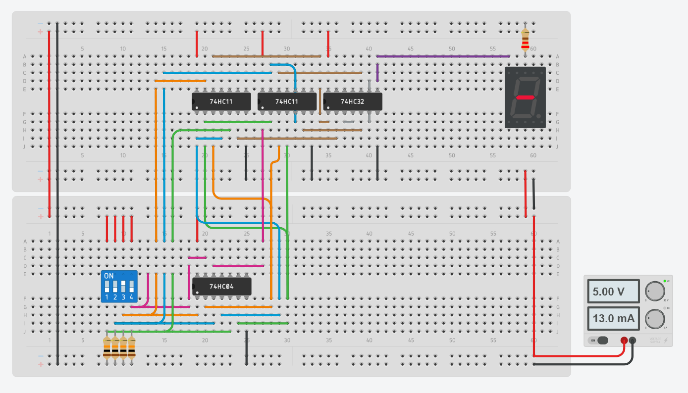
This is a formula we can easily implement with logic gates to build a digital circuit:
Our digital circuit is built based on the results we gleaned from our Karnaugh map.