Learn this method to generate frequency sweep using a Xilinx DDS IP core v6.0.
In this article, we'll show you how to generate frequency sweep using a Xilinx DDS IP core v6.0. This frequency sweep waveform can be utilized to test the frequency response of digital filters. The frequency in this chirp signal is increasing from 1 MHz to 10 MHz in a time span of 10 microseconds, and the sweep repeats indefinitely.
Key Terms and Supporting Information
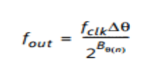
DDS IP core (PDF)Frequency sweepPhase incrementIn the code used to generate a chirp waveform, the module freqSweep is written in Verilog to instantiate the DDS IP core. Since a chirp waveform will be generated, a code is written in the freqSweep module to ramp up the phase increment. The streaming method is used under the DDS IP core to increment the phase. The phase increment for the standard mode of operation is calculated using this formula:
Where fout is the output frequency, delta(theta) is the phase increment, B (theta) is the number of bits used for phase increment, and fclk is the system clock frequency. In this code, a phase increment of 16 bits and an output of 8 bits each, for sine and cosine waveforms, is defined. By using the formula above for clock frequency of 100MHz, the phase increment for an output of 1MHz becomes 655—and 6554 for an output of 10MHz. The values above are rounded off to get an integer phase increment. In the main code freqSweep, all the DDS IP core parameters are instantiated. The input phase_tvalid is set to 1 to check the validity of the output data at a later stage.
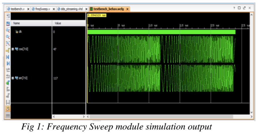
A clock frequency of 100MHz is generated in the testbench, which toggles every 5ns. At the positive edge of the clock, the code first checks the validity of the data by checking the existence of a value at nco_valid. It then outputs the sine and cosine waveforms that occupy the MSB and LSB bits of nco_data respectively. It later ramps up the phase increment value by 1 after a delay of 1.7 ns. This delay is a result of the difference of the phase increment, which spans over a period of 10us.
(10000ns /(6554-655)). After a delay of 1.7 ns, a new sine and cosine wave is generated with incremented frequency. After reaching the value of phase increment = 6554 for the output frequency of 10 MHz, the value of the phase increment is reset to 655, which produces an output of 1 MHz. This can be continued indefinitely for a very long simulation period. In this code, a simulation period is set to 20us, which gives two cycles of frequency sweep.
Code Listings
Main program:
`timescale 1ns / 1ns

module freqSweep(

input clk_in,

output reg [7:0] cos_out,

output reg [7:0] sin_out

);

// input system clock

//sine and cosine outputs

reg [15:0] pinc_stream ;

wire nco_valid;

wire phase_valid;

wire [15:0] nco_data;

//initialization of

//phase increment and

//phase valid input

//and nco data and

//data valid output

assign phase_valid = 1;

initial begin

pinc_stream = 655;

end

//phase increment

//value for 1MHz

dds_streaming nco1(

.aclk(clk_in),

.m_axis_phase_tvalid( nco_valid ),

.m_axis_data_tdata( nco_data ),

.s_axis_phase_tdata( pinc_stream ),

.s_axis_phase_tvalid(phase_valid)

);

//instantiation of DDS IP core

always@(posedge clk_in)

begin

if(nco_valid) begin

cos_out = nco_data[15:8];

sin_out = nco_data[7:0];

end

end

//display sine and cosine outputs for posedege

//of input system clock

always begin

#1.7 pinc_stream = pinc_stream + 1;

if (pinc_stream == 6554)

begin

pinc_stream = 655;

end

end

//incrementing the phase

endmodule
`timescale 1ns / 1ns

module testbench(

);

reg clk;

wire[7:0] cos;

wire[7:0] sin;

//input clock of 100MHz

//sine and cosine outputs

freqSweep deviceUnderTest(

.clk_in( clk ),

.sin_out( sin ),

.cos_out( cos )

);

//instantiation of freqSweep module

//100MHz source

initial begin

clk = 0;

end

always

#5 clk = ~clk;

//every 5 ns toggle clock

endmodule

freqSweep deviceUnderTest(

.clk_in( clk ),

.sin_out( sin ),

.cos_out( cos )

);

//instantiation of freqSweep module

//100MHz source

initial begin

clk = 0;

end

always

#5 clk = ~clk;

//every 5 ns toggle clock

endmodule
Output
Since the mode of operation used is the standard mode, the output obtained is close to the precise output.
Conclusion
This method is implemented to give a frequency sweep waveform, which is used to test various digital filters. This frequency sweep is a chirp waveform with an increase in frequency from 1MHz to 10 MHz, all n a timespan of 10us.