Make a power module small enough to be used in multiple projects while providing a range of common voltages.
Power sources such as batteries and power supplies are great when you project can directly use them. However, many circuits require regulation and specific voltages which makes power regulation circuits important. In this DIY Hacking project, we will make a power module that is small enough to be useful in other projects while providing a range of common voltages.
Schematic
How the Power Module Works
Power regulation circuitry can be found in most electronic products but when it comes to projects they can be inconvenient to integrate into the main circuit. With many projects now turning to modules, it makes sense to also “modulize” the power circuitry and this is the main aim for this circuit.
This circuit takes in an unregulated power supply (such as a battery or transformer), and produces different voltage levels suitable for most applications; 5V, 3.3V, and 1.8V. While 5V is very common in the hobby field, 3.3V devices are now becoming more common with one classic example being OLED displays. However, some devices (such as CPLDs) now require a 1.8V source which means that future projects may need to have as many as four different voltage levels!
Even CPLDs now need 1.8V for their core
Each one of the voltage regulator circuits contains the following features:
- Reverse protection diode (D1)
- Initial smoothing capacitors
- ESD protection diode
- Reverse voltage protection
- Output smoothing
- Pi filter
Reverse protection is crucial for protecting both the regulators and any device connected to the circuit and therefore realising this function is done with the use of D1 (only one diode is needed to protect the whole circuit). The next feature is initial smoothing and the purpose of initial smoothing is to ensure that the input voltage to the regulators never falls below the minimum input voltage. Many regulators do not like their outputs to be at a higher voltage than their input voltage and such an event could occur during an electrostatic discharge (ESD, e.g touching the output with your finger while statically charged). Therefore, a diode that connects the output and input is implemented such that when the output voltage goes beyond the input voltage the diode conducts and clamps the output voltage (D3, D4, D5).
With the regulators protected from large voltage spikes they also need protection from negative voltages that could potentially form on the outputs. This is easily done with a diode connected between ground and the power output in reverse polarity. Normally, the voltage output is more positive than ground and therefore the diode does not conduct but if the output should go more negative than ground then the diode will conduct and clamp the output to 0V.
The last piece of circuitry in each regulator circuit is a pi filter which consists of capacitors and an inductor in series. Capacitors are great for storing energy to release during voltage dips but inductors are great for resisting changes in current draw. While the science behind them will not be explained (for some pretty complex math, see here), a pi filter is great for filtering AC ripples in a power line. This is especially important in circuits that use low voltages (such as microcontrollers using the 1.8V line) as noise on the power line can cause unexpected behavior.
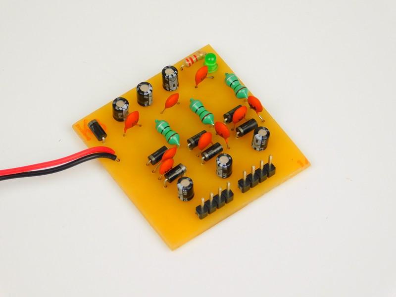
Construction
This circuit can be constructed using many different techniques including strip-board, breadboard, matrix board, and PCBs but it is recommended that the technique chosen is permanent. In this project I built a custom PCB using chemical etching and surface mount regulators instead of through hole regulators for the sake of space saving. The surface mount regulators are soldered on the underside of the PCB which is why there are no visible regulators on the top side.