This circuit will protect your devices from overheating and drawing too much current.
Creating a new project can be great fun but what about the first turn on? Nothing is more soul destroying than finding out that there is a short between the power lines. Never fear for the PPP is here! This circuit will protect your devices from overheating and drawing too much current.
Current Trip Circuit Schematic
Power Enable/Disable Circuit Schematic
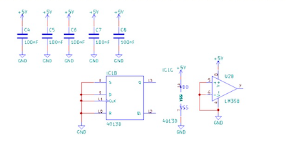
Power and Reference Schematic
How Does the Power Protector Work?
The circuit is designed to cut power to a circuit under test if the current flowing is too big or the current leaving the device is not equal to the current entering the device. Overcurrent is done with a simple current sense circuit whereas the current imbalance is done with an electronic RCD.
The overcurrent circuit is based around a sense resistor and a differential amplifier that trips the system when the current goes beyond a trip level. The differential amplifier (U1A and its nearby resistors), will take the two voltages SENSE- and SENSE+, and then produce a voltage that is equal to the difference between the two inputs. This voltage is then fed into U1B which is configured as a comparator so that when the differential voltage goes beyond the voltage of TRIP_LVL, the comparator will output a logical 1. This is then fed into a pull-up transistor Q1 which will set the flip flop IC1A. When this flip flop is triggered then Q\ turns off and therefore disconnects power to the output.
The RCD circuit is more complex than the overcurrent circuit as it needs to detect when the currents are not equal (either A > B or A < B). To do this, the voltage across the two sense resistors R18 and R22 need to be compared. The voltage across R22 can easily be used as one side is connected to ground whereas the first sense resistor is not. Therefore, an op amp (U2A) is used to steal the differential measurement from the overcurrent circuit. The two voltages are then compared using the differential amplifier U4A which also has an offset of 2.5V. This is done so that the output changes about 2.5V where 2.5V represents no difference. The RCD_DIFF signal is then fed, in parallel, to two comparators with U3A looking for a high imbalance, and U3B looking for a low imbalance. If either comparator is triggered, then the 4013 will be triggered and thus the output will be disconnected from the power source.
Resetting the circuit is done by pressing S1 which pulls the reset pin on the 4013 high and thus power is enabled to the circuit under test. You can set the trip level of the PPP by using the 4 way DIP switch which gives you various trip levels including 5mA, 10mA, 50mA, and 100mA.
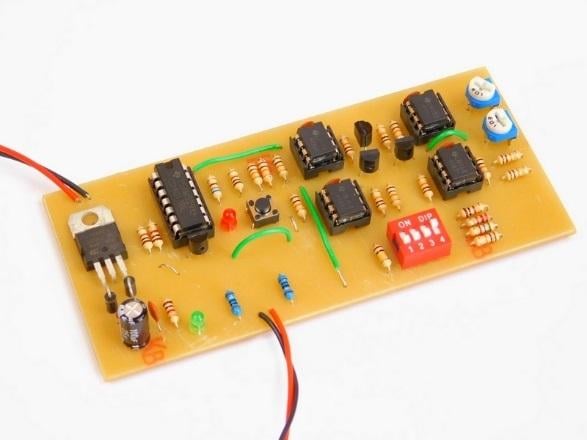
Construction
Constructing the circuit is easy and a PCB file is provided with the project files so that you can produce your own triple P. However, you can also use just about any circuit construction technique to build this circuit as all parts are of the through hole variety. This circuit could be incorporated into its own enclosure as a piece of test equipment where the indicators, reset button, and the power supply connectors, are taken to the front of a panel.