This article covers important drivers and proper circuitry required to safely connect external devices to an MCU's I/O.
As soon as you have an idea for a project, it is very tempting to jump right in and connect Arduinos and micro:bit devices to circuits and devices such as LEDs, relays, and speakers. However, doing so without proper circuitry can prove fatal to your microcontroller. Many I/O devices consume a lot of current (> 100mA), which most microcontrollers cannot supply safely and when they try to supply this amount of current they will often break. This is where special circuits called “drivers” come in. Drivers are circuits that can take a small weak signal from a microcontroller and then use that signal to control some power-hungry device.
For microcontrollers to properly work with external devices special circuits are sometimes needed. These external devices include:
- Driver circuits
- Input protection circuits
- Output protection circuits
- Isolation circuits
So, let’s take a look at some of these circuits and see how they work!
Simple LED Driver
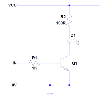
This simple circuit is handy for controlling high powered LEDs by microcontrollers where the microcontroller output is connected to “IN”.
Example of a simple LED driver
When the microcontroller outputs a 0 then the transistor Q1 turns off and so does the LED D1. When the microcontroller outputs a 1 then the transistor turns on and therefore D1 also turns on. The value of R1 depends on the output voltage of your microcontroller but values between 1KΩ ~ 10KΩ often work well. The value of R2 depends on the size of the load that you are powering, and this circuit is suitable for powering devices up to 1A at most.
Simple Relay Driver
Devices that need to consume more than 1A of current and will only be switched on and off once every few seconds may fair better with a relay.
While relays are fairly simple in design (a small electromagnet that attracts a metal arm to complete a circuit), they cannot be driven directly by a microcontroller.
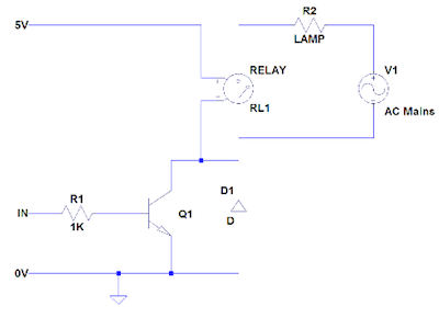
Common relays require currents around 60mA ~ 100mA which is far too much for most microcontrollers and so relays require driving using a transistor driving circuit (as shown above). However, instead of a resistor needing to be used to limit current a reverse protection diode is needed (D1).
When the microcontroller (connected to “IN”), outputs a 1 then the transistor Q1 turns on. This turns on relay RL1 and the result is the lamp (R2), turning on. If the microcontroller outputs a 0 then the transistor Q1 turns off which disables the relay and therefore the lamp turns off.
Relays are very common in circuits needing to switch AC mains circuits and relays are available for 230V 13A device switching (suitable for toasters, kettles, computers, and vacuums).
Example of a simple relay driver
Button Input
While connecting a button to a microcontroller should be simple problems can sometimes creep-up. The first (and most irritating problem), comes in the form of debounce which is when a button sends many signals when pressed and released.
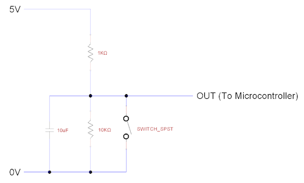
Buttons are usually a piece of metal that make contact with some other metal when pressed but when buttons make contact they often bounce (albeit a tiny one). This bounce means that the button connects and disconnects several times before settling and the result is an output that briefly looks random. Since microcontrollers are very fast they can pick up this bounce and perform button press events multiple times. To get rid of bounce, a debounce circuit can be used. The circuit shown here is a very trivial debounce circuit that works well and is simple to construct.
Example of a debounce circuit
Input Protection: Voltage
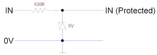
Not all input devices will be friendly to your microcontroller and some sources may even cause damage. If you have input sources that come from the environment (such as a voltage probe, rain gauge, human touch), or input sources that can output voltages greater than what the microcontroller can handle (inductor circuits for example), then you will need to include some voltage input protection. The circuit shown below uses 5V Zener diodes to clamp input voltages so that the input voltage cannot go above 5V and below 0V. The 100R resistor is used to prevent too much current flowing when the Zener diode clamps the input voltage.
Example of voltage input protection
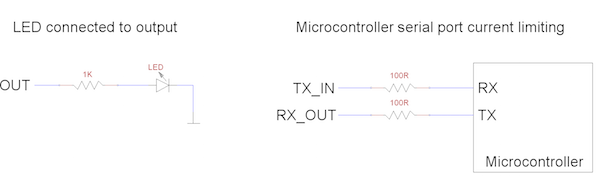
Input/Output Protection: Current
Inputs and outputs of microcontrollers may sometimes need to be protected from too much current flow. If a device such as an LED consumes less current than the maximum current output from a microcontroller then an LED can be directly connected to the microcontroller. However, a series resistor will still be needed as shown below and common values of series resistors for LEDs include 470Ω, 1kΩ, and even 2.2kΩ. Series resistors are also useful for input pins in the rare chance that the microcontrollers pin malfunctions or the input device experiences a surge of output current.
Example of using a series resistor for current protection
Level Converters
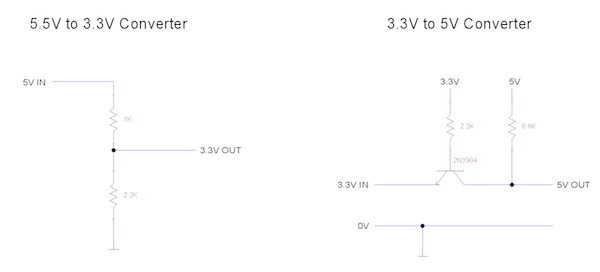
In the past, most signals in a circuit would operate on the same voltage and this voltage was typically 5V. However, with the increasing technological capabilities of modern electronics the voltage supply for newer devices is reducing. Because of this, many circuits incorporate mixed signals where older parts may operate at 5V while newer parts operate at 3.3V.
While many designers would prefer to use one single voltage level the truth is that older 5V parts may not be able to operate at 3.3V while newer 3.3V devices cannot operate at the higher 5V voltage. If a 5V device and 3.3V device wish to communicate then level shifting is needed which converts one voltage signal into another. Some 3.3V devices are 5V tolerant which means that the 5V signal can directly connect to the 3.3V signal but most 5V devices cannot tolerate the 3.3V. To cover both instances the circuits below show both a 5V to 3.3V converted and vice versa.
Examples of level converters
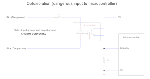
Isolation: Optoisolator
Sometimes the circuit that a microcontroller needs to interact with may pose too many issues such as electrostatic discharge (ESD), wide voltage swings, and unpredictability. In such situations, we can use a device called an optoisolator which allows two circuits to communicate without being physically connected to each other using wires.
Optoisolators communicate using light where one circuit emits light which is then detected by the other circuit. This means that optoisolators are not used for analog communication (voltage levels for example), but instead for digital communication where the output is either on or off. Optoisolators can be used for both inputs and outputs to microcontrollers where inputs or outputs could be potentially dangerous to the microcontroller. Interestingly, optoisolators can be used for level shifting too!
Example of using optoisolation to protect your microcontroller