Here, I can cover how to measure voltage, current, resistance, check if transistors work, continuity testing, and all!
A multimeter is a measurement tool that can come in very handy for troubleshooting electronics projects. In this tutorial, I’ll introduce what a beginner needs to know to get started with a multimeter.
What is a Multimeter and What Does it Measure?
A multimeter is a combination of a voltmeter, ammeter, and ohmmeter and works as a piece of standalone test equipment. It’s not limited to only these three measurements — it can also measure capacitance, frequency, and gain of transistors.
These meters were invented back in the 1920s and are still used as they provide high accuracy and have the capability to measure quantities in micro and nano ranges. These electronic meters are of two types: analog and digital. Digital meters are used widely because of their capability to display data in decimals.
Types of Digital Multimeters
There are two types of digital multimeters (DMM): auto-range and manual range. As per the name, in manual range DMMs you have to select the range of your measuring entities. This type of DMM is very cheap compared to auto range multimeters, Auto-range DMMs don’t have any protection circuits and if they’re misused, they could blow up.
The Parts of a Digital Multimeter
Even the most basic DMM has the following entities:
- Voltage (DCV and ACV or 〜)
- Current(A)
- Resistance(Ω)
- Capacitance(F)
- Continuity
- Diode test
Some of the other parts include:
- Probes: A DMM has two probes — one red and one black. Each has a plug and a metal strip used to connect your DMM to the electronic components you are measuring.
- Dial: The dial is used to select the measuring entity. These entities vary based on the type of DMM used.
- Display: The display shows a digital reading of the measuring entity and displays negative (-) sign.
- Slots: The slots are used to connect two probes (different multimeters have a different slot configuration for the RED probe):
The COM slot is just a common or ground port where the black probe is always connected.
The red probe connects to the VΩmA slot only when you are measuring voltage, resistance, current (less than 200mA), capacitance, continuity, or diodes.
The 10A slot is used when you want to measure currents higher than 200mA. Checking other entities using this slot won't harm the DMM but will give incorrect results.
Performing a Continuity Test
A continuity test checks whether two points of measurements are electrically connected or not. If both points are connected, then a beep generates, indicating continuity between two points.
For a simple continuity test measurement, connect both red and black probes with each other.
The continuity test checks for resistance between two points. If the resistance is less than a few ohms (Ω), it passes the continuity test and displays a small resistance value. If the resistance is large or there is no connection between the two points, it won’t pass the continuity test and displays 0L.
This test can be used for various purposes. It can be used to trace tracks on PCBs or check whether two or more electronic components are connected or not.
It can also be used to troubleshoot faulty ICs by performing a continuity test on the Vcc and Gnd pin. If a continuity test is passed, the IC can be considered faulty.
Measuring Voltage
Voltage is nothing but a measurement of the potential difference between the points. The two points can be leads of a battery, a resistor or any other electronic component.
Voltage has to be measured parallelly across any component. Let's look at an example of an LED driver circuit and measure the voltage across the resistor.
To measure the voltage across the resistor, place the red probe on the resistor end which is connected to the positive side of the battery, and the black probe on the other end of the resistor. This shows voltage drop across a resistor.
Now what if you switch probes? Don’t hesitate to test this oou. It will still display the same voltage value but with a negative sign. This negative sign indicates that measurement was done opposite to the direction of the current.
Let’s measure the AC volts coming from a house outlet. In India, we get a 230V AC signal with a 50Hz frequency.
First, place the dial at 750V AC and then plug the red and black probes inside the socket (position doesn’t matter) to read the voltage. This reading will have some tolerance of 土5% as there are other loads connected to it.
Measuring Current
To measure current, plug the red probe into the amps (A) slot to be on the safer side since we don’t know the value of current. If we get a very low value then we can go to milliamps.
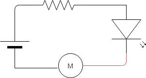
Now to measure the current of a circuit, we have to connect the multimeter in series with the circuit. To connect it in series, we have to physically break the connection. Refer to the diagram below.
Place the dial on 20mA and plug the multimeter’s black probe into the negative side of the battery and the red probe to the cathode of the LED.
Like when measuring voltage, switching probes won’t harm the meter and displays the magnitude with a negative sign.
It’s always a good practice to calculate current theoretically first and then measure current through multimeter. This way, you might save the fuse of the multimeter.
Measuring Resistance
Resistance is the property of an electronic component to oppose the flow of current. It is measured in ohms. Color codes are provided on each resistor to determine the resistance value. If you are not comfortable with doing calculations, the multimeter becomes a very helpful tool for you.
This DMM can measure 0-400MΩ of resistance. This measurement display can show three readings: 1, 0.00, or the actual resistance value.
- If the dial selected is in the range of the resistor, it displays a proper reading.
- If it shows 1 or OL. it means that the resistor is of a higher value, so you have to increase the range.
- If the multimeter reads 0.00, you have to lower the range and re-check.
Performing a Diode Test
A diode is a semiconductor element that conducts only when it is forward biased. Forward biasing is achieved by connecting the anode to the positive end and the cathode to the negative end of the battery/source.
This test determines a diode’s polarity and the forward voltage drop across it. Place the dial to the diode symbol and connect the DMM parallel to the diode.
Once the multimeter is connected to the diode in this configuration, the multimeter passes a small current through it. Diodes only conduct in a forward-biased region, and connecting the diode in such a manner displays a forward voltage drop.
The reading shown is in mV
Apart from the diode, we can also check a transistor’s voltage drop in the same manner and determine whether it is faulty or not. LED can also be checked by connecting it in the same way.
Note: If we switch a multimeter’s probe, it will show 0L. because the diode doesn't conduct in a reverse-biased condition.