Learn how memory chips can offer an alternative to logic gates to represent logic functions in circuit design.
Logic gates can be utilized to implement complex logic functions in a circuit, but doing all the necessary calculations can be a tedious and time-consuming process. However, memory chips can serve as a simple alternative because they can also be used to represent logic functions. In this article, I’ll discuss both approaches as well as a few pros and cons of them.
The Example Circuit
Throughout this article, I’ll use the same simple example: I want to design a circuit that takes four digital inputs and then displays the corresponding decimal number on a seven-segment display.
Keep in mind that there are many seven-segment controllers available that you can buy that do this job for you. However, I think this is the perfect example because you have to come up with seven different formulas and use quite a few logic gates, so using an EEPROM makes sense in this case.
The Traditional Approach to Logic Gates
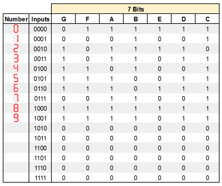
Let’s first take a look at how the circuit mentioned above could be designed with logic gates in mind. Typically, you start by creating a truth table that contains all relevant combinations of your input signals, as well as the corresponding value of the output with that combination. In this example, it looks like this:
Step one: a truth table containing all relevant combinations of your input signals and the corresponding value of the output with that combination.
As you can see, each number is represented by a unique combination of the four input signals. A through G are the outputs of the logic circuit that will connect to the corresponding inputs on a seven-segment display.
Calculating the Output Functions
After creating the truth table, you have to determine a logic function for each output that exactly matches the values of the truth table for each combination of the input signals.
If you look at the input “1000” in the table above, the output G has to be high, and for the input “0000”, the result of G is low. I’ll only outline the process for one output function. The other ones can be calculated in the same way.
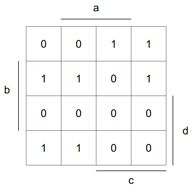
The easiest way to find a logic function that describes the behavior of G is to create a Karnaugh map and then simplify it.
In the next step, a formula that describes G can be derived from the map:
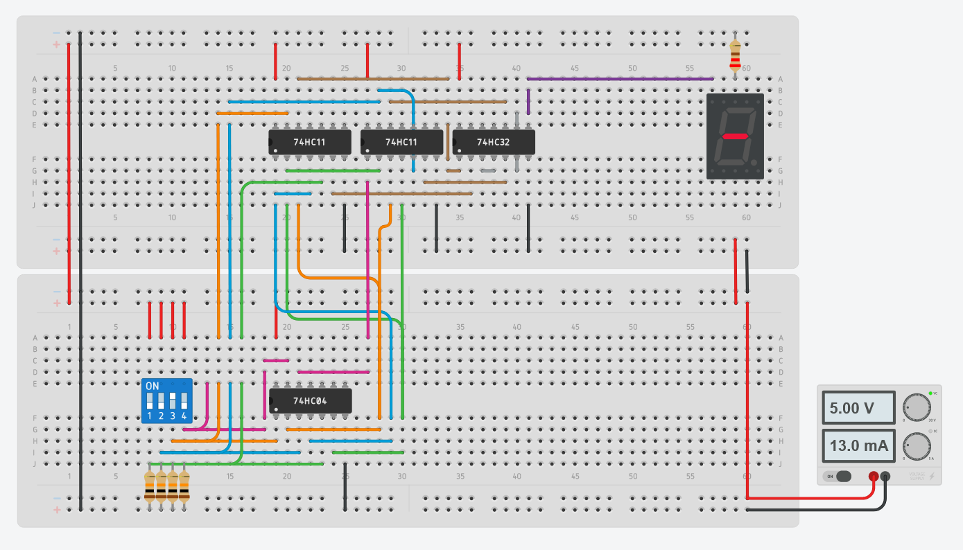
Once that’s done, you can implement the logic circuit for that single segment:
Implementation of the logic circuit for a specific segment.
Note that you have to repeat the entire process for every single segment of the display. The resulting logic circuit will, therefore, become quite complex — especially if you consider how simple the task is that it performs.
An Alternative to Logic Gates: Using a ROM Chip
In some cases, it may make more sense to replace the entire logic part of the circuit with a simple memory chip. Note that any memory chip will work. However, only persistent memory types, like ROMs or Flash memory, make sense in the real world because the volatile memory chips won’t retain the stored data when they are powered off. That said, any parallel ROM chip with at least four address and seven output lines, like the AT28C64B, will work just fine.
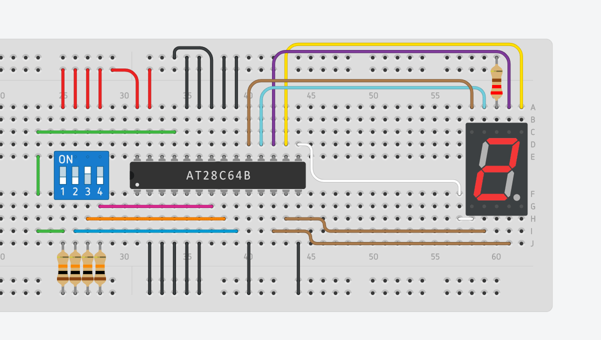
The four inputs (A to D) get connected to any four address lines of the EEPROM. The seven segments of the display (A to G) connect to any seven data lines of the EEPROM:
Connecting the display to the EEPROM.
Make sure that you adjust the data-bits to the pins you chose to use. I chose to arrange the four outputs in an order that makes it easier to connect the EEPROM to the display.
Once you made all the physical connections, you just have to store the values of A through G in the EEPROM at the correct address:
Address (A12-A0) | Data (I/O7-I/O0) |
|---|
0000 0000 0000 | 01111110 |
0000 0000 0001 | 00010010 |
0000 0000 0010 | 10111100 |
0000 0000 0011 | 10110110 |
0000 0000 0100 | 11010010 |
0000 0000 0101 | 11100110 |
0000 0000 0110 | 11101110 |
0000 0000 0111 | 00110010 |
0000 1000 0000 | 11111110 |
0000 1000 0001 | 11110110 |
The data values can directly be taken from the truth table that we created earlier.
Why Use Logic Chips at All?
If memory chips can be used to represent this behavior, then why go through all the hassle to calculate the logic functions and build a complicated circuit? The most important reason that comes to my mind is the price. ROM chips are usually quite pricey (around ten times the cost of simple logic ICs) and, most of the time, you won't use a lot of the storage space.
Furthermore, memory chips are much slower than logic ICs. Reading a value from a typical ROM will take around 150 nanoseconds, while the propagation delay on a typical logic IC is around five nanoseconds.
On the other hand, if you use a ROM chip, you can easily correct mistakes in your design by simply reprogramming the memory chip. Furthermore, a single chip uses less valuable board space on a PCB.
Choose Based on Your Top Requirements
Many complex logic circuits can be replaced by a single ROM chip. However, ROM chips are typically much slower and more expensive than logic ICs. Therefore, it only really makes sense to use ROM chips in circuits with many inputs and in circuits where speed isn’t important.