This article introduces the different types of capacitors available and the role each type of capacitor plays in design.
Like resistors, capacitors are the bread and butter of all electronic circuits and it is almost impossible to not have a capacitor in a practical circuit. Capacitors come in all shapes and sizes and are useful in specific scenarios depending on their type.
A capacitor is a component containing two electrically-separated plates. These plates can store charge and, depending on the circuit they are in, can be used to smooth out wobbles in power lines, remove DC voltages, remove AC voltages, and tune frequency circuits.
The material between the two plates is an electrical insulator and can be any material. However, the material chosen affects how the capacitor behaves. For example, electrolytic capacitors have an electrolyte between the plates which allows them to store more charge than ceramic capacitors but due to their larger ESR (equivalent series resistance), they take longer to deliver their charge.
Capacitors are always labeled with the symbol “C” followed by a number. The number indicates which capacitor it is in the schematic.
Non-Polarized Capacitors
A non-polarized capacitor is a capacitor that has no polarization. For example, batteries have a positive and a negative terminal and must be inserted in the correct way and polarized capacitors also have a positive and a negative terminal which means they must be inserted in a specific way. Non-polarized capacitors do not have this and can be inserted in any orientation.
Ceramic Capacitors
Ceramic capacitors are the most commonly used capacitor in the industry and come in many different shapes and sizes. In the past, the most commonly used capacitors were disc ceramic capacitors—these are still in mass production and used heavily in prototyping.
Modern mass-produced electronics no longer use ceramic disc capacitors because they require manual insertion and soldering. They now use SMD (surface-mount device) ceramic capacitors that look like small beige blocks. Such capacitors are used in power line decoupling near ICs, analog circuitry, and for filtering AC/DC.
Examples of ceramic capacitors on PCBs.
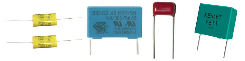
Film capacitors
Film capacitors (also known as polymer film capacitors), are large rectangular capacitors that often find themselves in power situations. Unlike ceramic capacitors, film capacitors are rated to high voltages. Their larger capacitances and non-polarization make them particularly useful in mains AC circuits.
Film capacitors often have capacitances between 100pF and 20μF, voltage capabilities between 100V and 2000V, and have low ESR (equivalent series resistance) and ESL (equivalent series inductance). Such capacitors use plastics such as PP, PET, PPS, and PTFE as their dielectric material. Common colors for film capacitors are yellow, blue, red, and green and while most are rectangular some are rounded rectangular.
It is entirely dependent on the manufacturer whether film capacitors have any details—including their capacitance and part number—printed on them.
Polarized Capacitors
Polarized capacitors are capacitors that have positive and negative terminals which means they must be inserted in a specific orientation. They are almost never found in AC circuits (as AC circuits have both positive and negative voltages), but are sometimes found in audio coupling for small speakers and microphones.
Unlike film and ceramic capacitors, polarized capacitors can hold large amounts of charge and find themselves most often in DC power situations including power supplies, welding equipment, buffering, and flashtube ignition. Polarized capacitors also come in different shapes and sizes and many are worth salvaging as they can be somewhat costly and difficult to obtain.
Aluminum Electrolytic Capacitors
Aluminum electrolytic capacitors come in several different packages both in SMD and through-hole varieties.
Despite many components these days being SMD (including electrolytic capacitors), through-hole aluminum electrolytic capacitors are still used. One of the reasons for this is that the physical size of a capacitor is often proportional to its capacitance and so capacitors greater than 100μF will be too large to be an SMD component.
Through-hole parts are physically stronger than SMD components as the through-hole plate has the top layer, bottom layer, and hole as mechanical anchor points whereas SMD components only have the top layer (which can be peeled off). At the same time, however, through-hole components can protrude off the surface of the PCB which can result in a lever action (and therefore can be easily “knocked off”).
While aluminum electrolytic capacitors offer large capacitances at low prices they do have some issues. One of the biggest problems is their large ESR (equivalent series resistance), which makes them “slow” to react to sudden changes.
Through-hole Capacitors
Through-hole capacitor varieties can either be axial (component leads on the ends), or radial (component leads underneath), and have a negative strip that indicates which pin is the negative lead. They will almost always have information printed on them including their operating voltage and their capacitance.
Radial electrolytic capacitors may also have a special cross indent on the top metal disc; this is a pressure relief disc that ruptures if there is a fault and the capacitor begins to expand due to gas build-up.
Examples of through-hole capacitors.
SMD Capacitors
SMD capacitor varieties are small tin cylinders with a small plastic square base. The negative lead is identified with the thick black mark on the top of the cylinder and these capacitors also have information printed on them.
Unlike the through-hole varieties these do not have the cross pressure relief system and this is most likely due to the fact that the low voltage / low capacitance combination means that during failure they produce little gas.
Tantalum Capacitors
Tantalum capacitors are electrolytic capacitors that use a tantalum pellet surrounded by its oxide as the dielectric and then surrounded by either a liquid or solid electrolyte as the cathode. Tantalum capacitors can have very high capacitances for their size due to the use of the oxide layer as the dielectric, have an excellent frequency response, are very reliable, and have a wide operating temperature range.
However, tantalum capacitors are very intolerant of reverse voltages and have been known to catch fire in some situations. They are also not able to handle ripple voltages too well and so designers must take extra care when using them in ripple applications.
SMD varieties of tantalum capacitors are more common in older designs (as early components could not handle reflow soldering) and are often rectangular with a yellow body. Through-hole varieties are also yellow and will be beaded in shape. The positive lead on the through-hole variety can be identified by the + marking above the positive pin and the SMD positive lead can be identified with the solid bar next to the connector.