This article introduces commonly-used inductors and discusses the uses of each type.
Inductors and chokes (which are a type of inductor) are two-terminal passive components in analog circuits and provide filtering, tuning, and spike suppression.
When inductors with mutual conductance are used together, they form transformers and provide isolation as well as step up/down capabilities. Inductors come in all shapes and sizes in both SMD and through-hole packages and some are not entirely easy to identify at first glance.
Inductors and Chokes
Let’s nail down the different cases in which an inductor or choke could be used before we take a look at the different types of each component.
An inductor is a passive electronic component that is designed to store energy in the form of a magnetic field. When current passes through an inductor a magnetic field is generated and when this current stops the magnetic field collapses which re-induces a current. Inductors are very useful in situations that may see sudden changes in current as the inductor will try to resist any changes.
Chokes are a specific type of inductor, are specifically used to block high-frequency AC signals while allowing low-frequency DC signals to pass. Chokes are most commonly found in electronic filters and when combined with capacitors, they create tuned circuits.
The easiest way to identify an inductor is via the PCB identification letter “L”.
Axial Inductors
Axial inductors can often be easily identified due to their color but can often be mistaken for resistors.
Just like axial resistors, axial inductors have colored bands that indicate the size of the inductor as well as its tolerance. The physical size of the inductor is often related to the power capability of the inductor and the inductance. There are two main distinguishing features of axial inductors:
- Their body is usually green/turquoise
- They have very low resistances
An example of an axial inductor. Image courtesy of Mouser.
If, for example, you saw an axial component whose color band suggest that it is a 10kΩ resistor but it has a recorded resistance of 1 ohm then there is a good chance that the component is, in fact, an inductor.
Axial inductors in an RF unit.
Air Coil Inductors
Air coil inductors are often easily identifiable due to their coiled appearance. However, some are very small and housed inside a glass tube while others can simply be the exposed coils. Although they bear a physical resemblance to chokes, they are much smaller and/or do not have a core.
Air coil inductor. Image courtesy of Mouser.
Air coil inductors are common in radio circuits because they provide tuning for high frequencies. However, only the glass-housed inductors are worth salvaging because coiled wires can easily be made.
Radial Inductors
A radial inductor has a similar design to radial electrolytic capacitors whereby the inductor stands upright on the PCB and has two legs protruding from the bottom. This type of inductor can sometimes be used as a choke depending on the function, and they often have higher inductances than air coils and axial inductors.
Unshielded radial inductors. Image courtesy of Mouser.
Radial inductors are available with either a core or no core and some have their inductance value printed on the side. Normally designed for low power situations, this type of inductor can be found in a variety of applications including low power conversion and AC filtering.
Radial covered inductor. Image courtesy of Murata.
SMD Inductors
SMD inductors have contact points rather than protruding pins so they can be surface mounted. The size of these inductors varies but more often than not they are much larger than your average SMD resistor or capacitor.
The design of SMD inductors can vary but many are wire wound (a wire wound around a core). Some SMD inductors are fully enclosed and show no wires or other internal parts while others are open and show the internal structure. Their appearance depends on their application.
An SMD inductor. Image courtesy of Mouser.
Like radial inductors, SMD inductors can be used as chokes in switch mode power supplies but only for low power applications.
Toroidal Choke
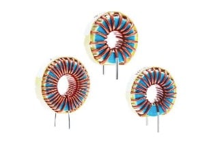
Toroid chokes come in all shapes and sizes but always have two leads and a core. These chokes are found in power supply applications and have inductances much larger than standard inductors.
Some toroid chokes may have multiple coils on the core but these are either transformers or common mode chokes. The number of turns on a toroid choke can vary and the thickness of the wire is a good indicator of the power rating of the choke.
Toroidal chokes. Image courtesy of Mouser.
Toroid chokes are worth salvaging as they can either be dismantled for the core or used as is in other projects. They almost never have any identification on them and so determining their inductance requires a testing tool.
Small toroidal choke hiding between two components.
Ferrite beads, or chokes, and rods are often used in small chokes that are designed for power filtering in low power situations. These come in different forms (but are often through-hole), have exposed wires, and will either be wrapped around the core or wrapped through the core.
Large ferrite beads can be found on cables such as power cables and USB cables which are designed to prevent noise entering an electronic circuit. Small ferrite beads are very cheap and not worth salvaging but the larger ones are more expensive (especially the clipped versions).
Some ferrite beads are housed in a clipped casing which allows users to attach them to any cable of their choosing.
Common Mode Chokes
Common-mode chokes consist of two coils wound in a particular way around the core. Often found in plastic packages, these chokes have four connectors instead of just two. Common-mode chokes are designed to allow two equal but opposite currents to pass through with ease while blocking common signals.
SMD common mode choke. Image courtesy of Mouser.
Common mode choke diagram.
Like normal chokes, common-mode chokes are often in series with a power supply. The two coils that make up the common-mode choke sit in series with both the power and ground (see the diagram below). Interference will most likely cause an equal change in both power lines (common-mode) and this is blocked by the common-mode choke.
Common mode choke with exposed coil. Image courtesy of Mouser.