Learn about the different types of one of modern electronics' biggest advancements: integrated circuits (ICs).
Before integrated circuits came about, discrete circuits made up of transistors, resistors, capacitors, and inductors were the norm in circuit design. Integrated circuits combine many of these components into a single piece of silicon, greatly reducing the size of circuits while increasing their power and complexity.
Modern electronics would not be where it is today if not for the silicon chip, so in this component identification guide we will learn about identifying ICs.
ICs are Easily Identified
Out of all components to identify, integrated circuits are one of the easiest components to identify due to their many pins and packages. Integrated circuits are composed of many different types of circuits, such as an amplifier for an audio signal (LM358), a logic chip for quick processing of logic signals (40xx and 74xx), or a microprocessor for a computer (Z80, Broadcom BCM2836).
Through-hole integrated circuits are only ever found in dual inline packages (DIP) but SMD integrated circuits are found in a wide variety of packages. Integrated circuits are identified with the idents IC or U.
Through-Hole ICs
As stated before, through-hole ICs are only found in DIP packages (some USSR ICs had very unusual packages but these are incredibly rare to the point where most people never encounter these).
The first DIP packages were made of a ceramic material (that would be either black or white) and later used plastic.
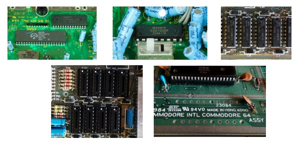
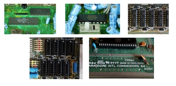
DIP parts are very easy to identify with their equal number of pins on the two longer sides and have their details printed on the top case. Identifying the left-hand side of the IC is done by looking for a notch on the top of the package. The top left pin is pin 1, which is sometimes identified with a small dot next to it.
Clockwise from top left: A Z80 in a DIP package, CXA1034P, 1-bit RAM chips, IC sockets, and an IC in a socket.
While DIP technology is no longer a preferred package type for mass-produced consumer devices (due to its size and cost), it is still widely produced. This is for a few reasons: the ease of prototyping, the repairs of older equipment, and the hobby market may still provide enough revenue to justify producing them.
Many modern microcontrollers are still available in DIP packages including PIC16, PIC18, PIC24, PIC32, ATmega, and even STM. Most DIP ICs used in mass production are soldered directly onto the PCB but some may be inserted into sockets. Sockets look like ICs except they are hollow and have pin acceptors for inserting an IC.
Through-Hole/SMD Hybrid ICs
Some ICs can be found in a special package called leaded chip carrier (LCC) but the number of these devices on the market is very low.
The IC itself can be considered a surface mount part as there are no through-hole pins but at the same time they are somewhat similar to through-hole parts. While their pin spacing is the same as SOIC (1.27mm or 0.05” between pins), they are mostly used in sockets that are through-hole.
Unlike DIP parts, LCC parts are housed in packages with connectors on all four sides of the package, providing more pin connections for circuits. These parts where common with CPLDs and other high I/O count devices but are no longer used in mass production.
An LCC package on a monitor and a CPLD in a hobby-made graphics card
An LCC package on a monitor (left) and a CPLD in a hobby-made graphics card (right).
SMD ICs
SMD ICs are available in a huge range of packages but they often have two common features:
- They contain many pin contacts
- They are almost always black in color
Since there are so many different packages only the most common ones will be introduced here, but many other packages are variations of the ones covered.
SOIC and SOP
Small outline integrated circuits (SOIC) and small outline package (SOP) ICs and are one of the easiest SMD parts to use in prototyping and hobby projects.
While they are up to 70% smaller than DIP parts they are still large enough to be handled with ease and their pins are separated by 1.27mm.
SOIC and SOP ICs have their identification printed on the top of their bodies and often have a dot near pin 1. Component series such as the 40xx and 74xx can be found in these packages but so can many modern parts including microcontrollers. De-soldering these parts is possible, the most appropriate method being copper braid as opposed to solder suction.
Quad Flat Packages
The quad flat packages (QFP) are SMD outlines that have leads on all four sides of the package. These are commonly found on microcontrollers and microprocessors due to their high pin count and their small size.
The first type of quad flat pack devices had lead spacings similar to an SOIC which made them hobby friendly. However, the more common types such as the thin quad flat package (TQFP) or the low profile quad flat package (LQFP) ICs are not so easy to use.
One of the problems with TQFP and LQFP packages is that they are prone to solder bridges between pins as the pitch of the pins can be as small as 0.3mm. These parts have their part numbers and type printed on the top side and a small dot next to pin 1.
QFP examples on a variety of PCBs.
Quad Flad No Lead and MicroLeadFrame
Quad flat no lead (QFNL) and MicroLeadFrame® (MLF) packages are now one of the more common IC solutions for mass-produced devices as they are incredibly cheap and small.
Both ICs have contact pads on the underside along the perimeter, so they cannot be soldered using traditional methods. To solder or de-solder these parts, hot air is required to heat the PCB and IC in order to melt the solder on the PCB pads. Then the part can then be removed using tweezers.
These parts are not designed for prototyping nor are designed for removal and repair which makes them one of the most unfriendly packages to deal with as a hobbyist. Microcontrollers, microprocessors, CPLDs, complex analog devices, Wi-Fi modules, and much more are found using these packages.
A variety of QFNL and MFL IC packages.
One major benefit with QFNL and MLF packages is that they have part identifications printed on the top side so you are unlikely going to come across an IC that you cannot identify with Google.
Some QFN parts look like they have solder connections on the outside, making them look like TQFP. But note that these solder connections are either not connected to the pad and are just “spare” solder on the pad or they are soldered connections to the very outside of the package as some QFN parts have their connectors exposed on the outward face of the package.
Ball Grid Array ICs
Ball Grid Arrays (BGA) are IC packages that provide the densest pins with many hundreds of pin connections in very small packages. Their pins, however, are underneath the IC making them the most difficult type of IC to extract from a PCB.
Because of their size and density, BGAs are often found on microprocessors and SoC (system-on-chip), microcontrollers, and FPGAs. Small BGAs are also used in CPLD devices and in memory such as RAM. They are easily identifiable as they are thin rectangles that appear to float above the PCB with no visible solder connections and are available in square and rectangular outlines.
Examples of BGAs mounted on different PCBs, including a Raspberry Pi (center).
Chip-on-Board ICs
The chip-on-board is one of the most common types of IC mounting in mass-produced parts that do not use advanced microcontrollers or microprocessors.
These ICs are also the ultimate in difficulty for extraction. It’s practically impossible as the fundamental difference from other IC packages is that they don’t have a package!
The silicon die itself is bonded to the PCB directly and fine gold wires are attached between the die and PCB. The die and connectors are then submerged under a black epoxy that protects them from damage. This method is the cheapest for mass-produced products using low-cost ICs and is very popular in China-made products. The best method for removing the epoxy to see the die is to use a heat gun to cook the epoxy until it easily breaks off.
A few examples of chip-on-board ICs. They may look messy, but they're effective!