If you’ve ever dipped your toes into digital electronics, you’ve probably stumbled on something called an SR Latch. Sounds fancy, but really, it’s just a tiny memory element that can “remember” one bit of info. Think of it like the brain of a very forgetful goldfish: it only knows if it’s been told to “Set” or “Reset”.
In this post, we’ll walk through what an SR Latch is, check out the truth tables, and look at the basic, gated, and clocked versions. Don’t worry, it’s not as intimidating as it looks in textbooks.
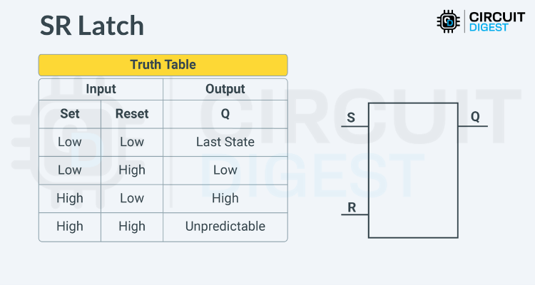
So…what is an SR Latch?
SR stands for Set-Reset. It’s a simple little circuit with two inputs, S (Set) and R (Reset), plus an output Q (and sometimes its evil twin Q̅, the inverted version).
Here’s the deal:
- If you “Set” it, Q goes HIGH (1).
- If you “Reset” it, Q goes LOW (0).
- If you leave it alone, it just holds on to the last thing it was told.
This makes it a basic memory element. The fun part is you can build one using NOR or NAND gates, but with NANDs the logic flips a bit (active LOW inputs).
Oh, and quick side note: when you hook a latch up to a clock signal and make it edge-triggered, it stops being a “latch” and graduates to “flip-flop.” Same family, different attitude.
The Truth Table (a.k.a. “What Happens When…”)
Here’s what goes down:
- Both S and R LOW → Nothing changes. Q just chills in whatever state it was before.
- S LOW, R HIGH → Q resets to 0.
- S HIGH, R LOW → Q sets to 1.
- S HIGH, R HIGH → Uh oh. That’s the “forbidden” state. Outputs go unstable. Don’t do this unless you like chaos.
A Quick Look at the Simulation
Here’s a NAND-based SR Latch in Proteus. Watch how Q and Q̅ switch around as you play with S and R. It’s basically electronic whack-a-mole.
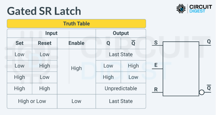
Gated SR Latch: Now With an Enable Button
Alright, so the vanilla SR Latch works, but sometimes you want more control. Enter the Gated SR Latch.
This one adds a new kid to the block: Enable.
- If Enable = HIGH, the latch behaves normally.
- If Enable = LOW, the latch ignores you and keeps its last state.
It’s like putting a lock on your latch.
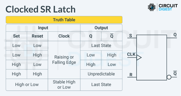
Clocked SR Latch (a.k.a. SR Flip-Flop)
Now we get fancy. Instead of Enable, we throw in a Clock input. That means the latch only pays attention when the clock edge ticks (rising or falling, depending on the design).
This makes it edge-triggered, which is a big deal in sequential circuits.
Truth table time:
- S = R = 0 → No change.
- S = 1, R = 0 → Q gets set to 1.
- S = 0, R = 1 → Q resets to 0.
- S = R = 1 → Same forbidden drama as before. Avoid.
But now, all this only happens on the clock edge. That’s why this is also called the SR Flip-Flop.
Wrapping It Up
So, that’s the SR Latch family tree:
- The basic version (Set and Reset only).
- The Gated version (with Enable).
- The Clocked version (aka SR Flip-Flop).
These simple little circuits are the building blocks for bigger memory systems and sequential logic. Master them now, and suddenly flip-flops and registers won’t look so scary later.
Got questions? Toss them in the comments or head over to the maker forums. Somebody out there has definitely wired an SR Latch backward at 2 a.m. and can sympathize.
This piece is based on this SR latch tutorial.