Make an Arduino flow rate sensor to measure water flow for a variety of applications.
Have you ever wanted to measure liquid flowing through a pipe or container, or to create a control system based on the water flow rate or quantity? For example, you could use this while gardening to measure the amount of water used to water your plants, to prevent wastage. If yes, then this easy DIY project is for you! Here are step-by-step instructions on how to measure water flow rate and quantity using an Arduino flow rate sensor.
How Does the Flow Rate Sensor Work?
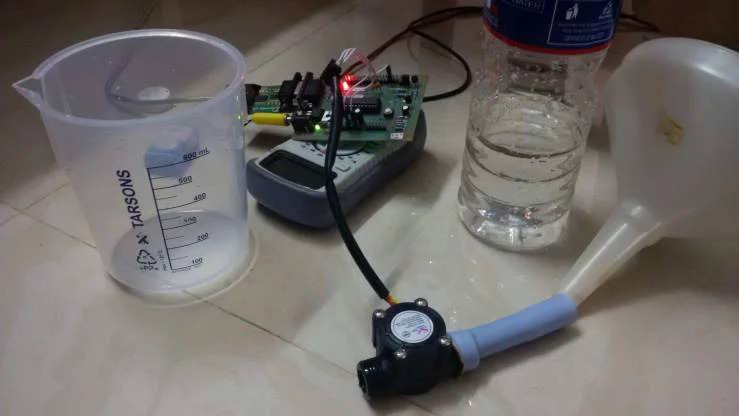
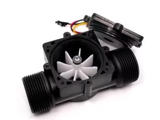
The Arduino flow meter works on the principle of the Hall effect. According to the Hall effect, a voltage difference is induced in a conductor transverse to the electric current and the magnetic field perpendicular to it. Here, the Hall effect is utilized in the flow meter using a small fan/propeller-shaped rotor, which is placed in the path of the liquid flowing.
The liquid pushes against the fins of the rotor, causing it to rotate. The shaft of the rotor is connected to a Hall effect sensor. It is an arrangement of a current flowing coil and a magnet connected to the shaft of the rotor, thus a voltage/pulse is induced as this rotor rotates. In this flow meter, for every liter of liquid passing through it per minute, it outputs about 4.5 pulses. This is due to the changing magnetic field caused by the magnet attached to the rotor shaft as seen in the picture below. We measure the number of pulses using an Arduino and then calculate the flow rate in liters per hour (L/hr) using a simple conversion formula explained in step 2.
Connecting the Arduino to the Flow Rate Sensor
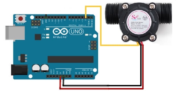
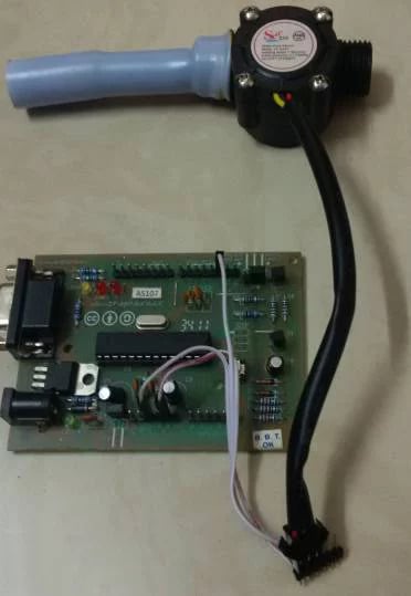
The connections required for this flow rate sensor with respect to the Arduino are very minimal. There are only three wires coming from the flow rate sensor. The 5V VCC (red wire), the GND (black wire), and the signal/pulse (usually yellow) line. Connect the VCC and GND of the flow meter to the Arduino's VCC and GND. The pulse line of the flow rate sensor is connected to the Arduino's digital pin 2. The Arduino's digital pin 2 serves as an external interrupt pin (interrupt pin 0). You have hooked up your flow meter to the Arduino!
Arduino flow rate sensor connections
Uploading the Flow Meter Code to the Arduino and Measuring Water Flow Rate
Upload the Flow Meter Code to your Arduino. The code uses an external interrupt on the Arduino's digital pin 2. This is used to read the pulses coming from the flow meter. When the Arduino detects the pulse, it immediately triggers the pulseCounter() function. This function then counts the total number of pulses.
In this Arduino flow rate sensor, for every liter of liquid passing through it per minute, it outputs about 4.5 pulses. Dividing the total pulse count by 4.5 will give you the total amount of liquid passing through it in liters per minute. Multiplying that by 60 will give you the flow rate in liters per hour, which gives us the total amount or quantity of water/liquid that has passed through it. The sensor is accurate to within 3%.
Here's a video showing the Arduino flow rate sensor in action!
Use this Arduino flow rate sensor with a solenoid valve to monitor and control the water used. You can use it in your gardening system, or interface it with an LCD display for other applications that require you to measure water flow rate and quantity. Have fun with your new Arduino flow rate sensor!