How the Ultrasonic Range Finder Works
Before we can learn about how our project can determine the distance from a distant object, we first need to understand what ultrasound is. Ultrasound is a sound wave whose frequency is beyond that of human hearing (usually greater than 20kHz). Because of its inaudible frequency and rarity in nature, ultrasound finds itself in many applications that involve distance measurements and imaging.
Ultrasound ranging and imaging work in a near identical way to SONAR (sound navigation and ranging), where a short burst of sound is emitted. This burst reflects off distant objects, and the resulting echoes are recorded. Since the speed of sound is known, as well as the time between the transmission of the burst and the resultant echo, the distance can be easily calculated using the age old formula D=SxT.
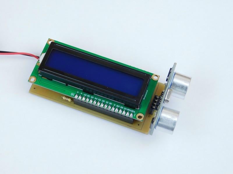
The core of our circuit is a PIC16F1516, which is connected to a 16x2 LCD module and an ultrasonic module. The first code executed by the PIC is configuration code, which configures the internal oscillators, peripherals, and IO ports. Once configured, the PIC enters an infinite while loop, which performs multiple tasks. The first of these tasks is to tell the ultrasonic module to make a ping. The second task is about waiting for the module to respond (it waits until echo goes high). The third task increments a timer while the echo input is high, and the last task is to determine the distance and then print the result onto the LCD.
Getting the module to send a pin requires a pulse (low to high) whose width is at least 10 microseconds (very easy to do on the PIC). Waiting for the echo signal to go high is easily done with a single while loop. Once the echo has gone high, we reset timer 1 and enable it so it begins counting. When a low signal is detected from the echo pin, we stop timer 1 and start our calculation. Timer 1 in our project is being clocked by Fosc/4, and since Fosc is 16MHz, the counter is operating at a speed of 4MHz. This means that the value in our counter does not relate to a nice time base, which needs to be fixed. By dividing the timer value by 4, we get a time in microseconds, because the counter is clocked at 4MHz (250ns clock pulse). Every four ticks correspond to 1 microsecond, so dividing by four gives us a counter that counts in microseconds.
Our speed is in micrometers per second (343), so using our speed and time together is simple — just remember that the answer has to be divided by two since the signal has to travel to the object and back. The distance answer that we get will be in micrometers, and if the answer is needed in meters, it can be divided by one million. In order to display the answer, we have to convert the number into an ASCII string, which we do by the function longToASCII (long number). This is a custom function and was written to keep memory and RAM usage as low as possible (since standard C libraries can very quickly eat up RAM and ROM), however, its functionality will not be explained here. (Though we encourage you to look at it and try to figure out how it works.)
Construction
This project uses parts that are all available in through-hole packages, which means you can use most circuit board construction techniques. This includes stripboard, breadboard, matrix board, and PCB. For the sake of convenience and the fact that my 7805 is a small SOT-89, I have used a PCB for this project, but most of the parts have been socketed. This means that parts such as the display and the IC can be reused in other projects. This is particularly useful since microcontrollers can cost several dollars each.
This project contains a display whose only purpose is to show the distance between an object and the ultrasonic module. However, it is not needed for functionality, and if removed, the circuit would be incredibly small, which means that many portable projects such as robots and wearables could incorporate the ultrasonic module. One problem that such modules face is interference from either other ultrasonic modules and/or ultrasonic sources; however, these are few and far between. If multiple ultrasonic sensors are needed, modules should be used one at a time, and the result from others should be ignored until you use them.