Warning
This project connects to the mains supply, and therefore poses a potential hazard. Therefore, this project is here to demonstrate how a basic PSU works as well as circuit considerations. This project should only be undertaken by those who are competent to work with mains electricity.
How Does the Power Supply Unit Work?
The mains voltage (depending on where you live) is typically too large for most circuits, and therefore needs to be reduced to a usable voltage (such as 12V). However, the mains electricity is a sinusoidal waveform about 0V, which means that even a reduction in the amplitude still leaves us with a constantly changing amplitude. Therefore, we have to take this waveform and adjust it so we get a steady voltage on our outputs.
The first part of the circuit (not shown on the schematic) is the incoming transformer, which is of the center tapped variety. If the center tap on the secondary is referenced as ground, we get two voltages that are opposite in magnitude such that if 12V is present on one of the outputs with respect to the center tap, then the other output has -12V. This allows us to create a split supply that has both negative and positive voltages, which is required by many circuits (those involving op-amps).
So, with our split transformer output, it's time to rectify this output, since each tap from the transformer will still produce both negative and positive voltages. This is done with the four diodes, D2, D3, D4, and D5. However, the rectifier output still has times where there is little or no output voltage. To solve this, the capacitors C3 and C7 are used, which are very large electrolytic types. These store and release charge as needed and convert the variable output from the rectifier into a more consistent voltage. At this point, we now have two power rails: one is positive with respect to ground, and the other is negative (but of equal magnitude to the positive rail) with respect to ground.
Since we need a variable output, the LM317 and LM337 have to be used in a standard configuration with protection diodes and all the required smoothing components. The values of RV1 and RV2 will determine the output voltage of their associated LM part, and thus provide a variable output that is regulated. It should be noted that these devices can get very hot, so a heat sink will not be a bad idea if you want currents beyond 100mA at the output. But during operation, there is no way to know what the voltages are from the outputs without measuring, so two voltmeters have been included in the design. The voltmeter that measures the positive rail is directly connected to the output of the LM317, but the voltmeter that measures the negative rail cannot be connected to the LM337, as it cannot measure negative voltages. To get around this problem, an inverting amplifier (U4A) has been used, which converts the negative voltage into positive and allows for the voltmeter to measure the negative rail. Our power supply also needs a pair of fixed voltages (for convenience), and so I chose a 7805 and 7905. The 7805 provides a +5V output while the 7905 provides a -5V output, and both parts have diode protection to prevent damage.
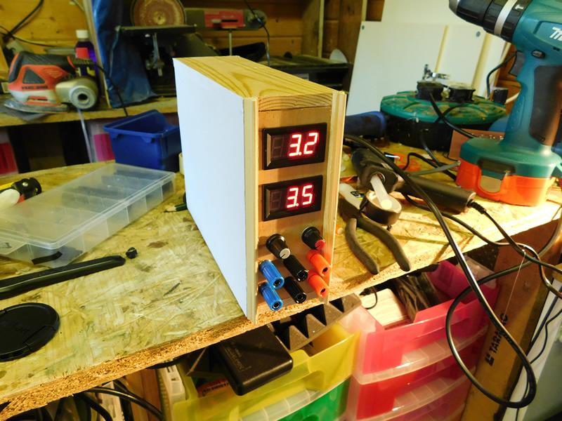
Construction
The power supply shown in this project can be built using many construction techniques but a PCB is the recommended method. This is due to the use of potentially large currents and voltages in use, which may be problematic on a breadboard or stripboard. I also recommend using a case made of an insulating material to prevent the risk of electric shock if internal wiring makes contact with the case. Note that this project is for demonstration purposes of a power supply and should not be undertaken by anyone who is not certified to work with and handle mains electricity safely.