How to use an ESP-01 module to control an LED over the internet, which allows you to control any electrical device.
In this ESP8266 tutorial, we are using an ESP-01 module to control an LED over the internet. The ESP8266 is a cheap, yet effective platform for communicating over the internet. It's also easy to use with an Arduino. After going through this ESP8266 tutorial, you will have the know-how to control any electrical device through the internet from anywhere in the world!
Here, we will be using an USB-to-TTL converter to program the ESP8266 ESP-01 module.And we'll be using the Arduino IDE to develop the web server to control an LED remotely. If you just bought your module, you can also refer my previous ESP8266 tutorial to see how to get started with the ESP-01 Wi-Fi module. It also shows how you can configure it and verify that there is communication established between the ESP8266 and another device without using aUSB-to-TTL converter.
How Does It Work?
The ESP8266 can be controlled from your local Wi-Fi network or from the internet (after port forwarding). The ESP-01 module has GPIO pins that can be programmed to turn an LED or a relay ON/OFF through the internet. The module can be programmed using an Arduino/USB-to-TTL converter through the serial pins (RX,TX).
Connecting the Hardware to Your ESP8266
We can either use a USB-to-TTL converter or use an Arduino to program the ESP8266. Here are three methods you can follow to upload the code to ESP8266 — select the one that suits you best. Refer to the following diagrams for each and set up the hardware accordingly.
1. USB-to-TTL Converter Using DTR Pin
If you're using a USB-to-TTL converter that has a DTR pin, uploading will go smoothly. Please be informed that the serial monitor will not work while doing this.
USB TTL ------> ESP8266 ESP-01 GND------------>GND TX-------------->RX RX-------------->TX RTS------------->RST DTR------------->GPIO0
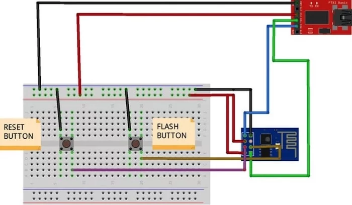
2. USB to TTL Converter Without DTR Pin
To connect the USB-to-TTL converter without the DTR pin, we have to use manual flashing. For this, we use two push buttons. Refer to the following diagram:
USB TTL ----------> ESP8266 ESP-01 GND---------------->GND TX------------------->RX RX------------------->TX Reset Button-------->RST Flash Button-------->GPIO0
While uploading the code, press the flash button. Keep the flash button pressed while you click once on reset. You may now release the flash button. The ESP8266 is now in flash mode! You will be able to upload the sketch now.
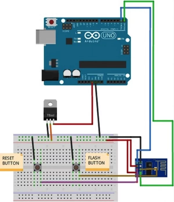
Using Arduino Uno to Flash the Code to the ESP8266
You can use the Arduino UNO to flash the code to ESP8266 ESP-01. While uploading the code, follow the same procedure to keep the flash button pressed while you click once on reset and release the flash button.
ARDUINO ---------------> ESP8266 ESP-01 GND---------------------->GND TX------------------------>TX RX------------------------>RX Reset Button------------>RST Flash Button------------>GPIO0
Uploading the ESP8266 Code
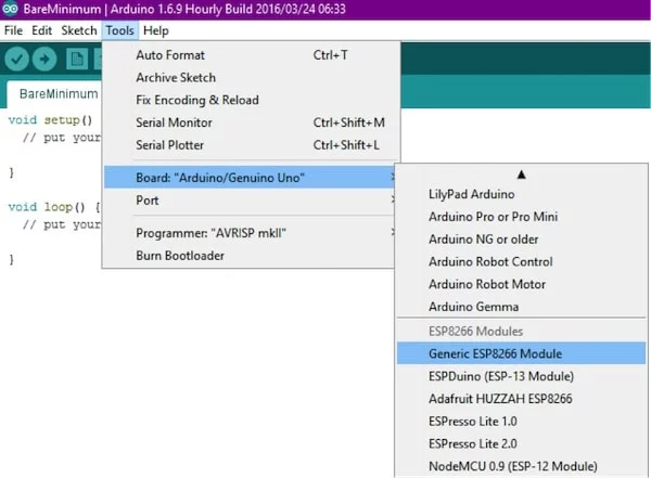
Use any one of the methods shown above and open the Arduino IDE, then select your ESP8266 board from Tools > Board > Generic ESP8266 Module.
Note: If you haven't installed the ESP8266 board setup for Arduino, do that by following STEP 2 of this tutorial. Then continue with this ESP8266 tutorial.
Now copy the code given below to the Arduino IDE and press the upload button. Change SSID into your Wi-Fi access point, and change the password to your Wi-Fi password and compile.
#include <ESP8266WiFi.h>

const char* ssid = "YOUR_SSID";//type your ssid
const char* password = "YOUR_PASSWORD";//type your password

int ledPin = 2; // GPIO2 of ESP8266
WiFiServer server(80);//Service Port

void setup() {
Serial.begin(115200);
delay(10);

pinMode(ledPin, OUTPUT);
digitalWrite(ledPin, LOW);

// Connect to WiFi network
Serial.println();
Serial.println();
Serial.print("Connecting to ");
Serial.println(ssid);

WiFi.begin(ssid, password);

while (WiFi.status() != WL_CONNECTED) {
delay(500);
Serial.print(".");
}
Serial.println("");
Serial.println("WiFi connected");

// Start the server
server.begin();
Serial.println("Server started");

// Print the IP address
Serial.print("Use this URL to connect: ");
Serial.print("http://");
Serial.print(WiFi.localIP());
Serial.println("/");
}

void loop() {
// Check if a client has connected
WiFiClient client = server.available();
if (!client) {
return;
}

// Wait until the client sends some data
Serial.println("new client");
while(!client.available()){
delay(1);
}

// Read the first line of the request
String request = client.readStringUntil('\r');
Serial.println(request);
client.flush();

// Match the request

int value = LOW;
if (request.indexOf("/LED=ON") != -1) {
digitalWrite(ledPin, HIGH);
value = HIGH;
}
if (request.indexOf("/LED=OFF") != -1){
digitalWrite(ledPin, LOW);
value = LOW;
}

//Set ledPin according to the request
//digitalWrite(ledPin, value);

// Return the response
client.println("HTTP/1.1 200 OK");
client.println("Content-Type: text/html");
client.println(""); //  do not forget this one
client.println("<!DOCTYPE HTML>");
client.println("<html>");

client.print("Led pin is now: ");

if(value == HIGH) {
client.print("On");
} else {
client.print("Off");
}
client.println("<br><br>");
client.println("Click <a href=\"/LED=ON\">here</a> turn the LED on pin 2 ON<br>");
client.println("Click <a href=\"/LED=OFF\">here turn the LED on pin 2 OFF<br>");
client.println("</html>");

delay(1);
Serial.println("Client disconnected");
Serial.println("");
}
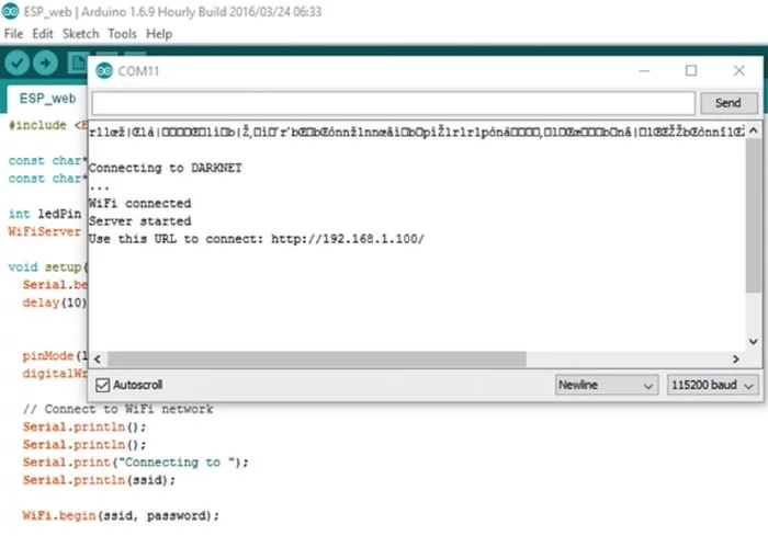
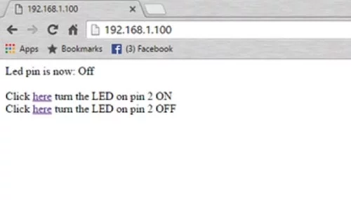
Open the serial monitor and open the URL shown in your serial monitor through your web browser. Connect GPIO 2 of the ESP8266 to the longer lead of the LED (+ve terminal). Now you can control the LED remotely through the internet!
Click on the respective hyperlinks in your browser to toggle the LED ON and OFF.
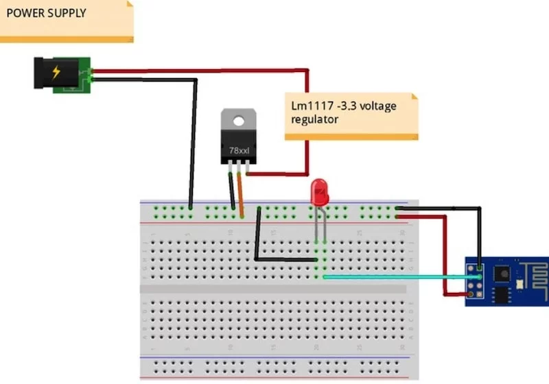
Remove all the wires that were required for uploading. Lm117 is used to provide regulated 3.3V output. This will let you make the ESP8266 or ESP-01 module stand alone.
Connecting the ESP8266 to the Internet
Currently, the ESP8266 module can only be accessed through the local Wi-Fi network. In order to control your devices from the internet, you have to do port forwarding on your router. To do this, find the IP address of your system either by using the "ifconfig" command on your terminal, or go to whatsmyip.org. Copy down your IP address. Now open your router setting and go to the "Forwarding" settings. Enter the details for the "Service Port" and "IP Address". The service port is the port number from your Arduino code (Service port: 80):
WiFiServer server(80);//Service Port
The IP address is the one you noted down before. Leave the other settings as default. Now go to your browser and enter the address: xxx.xxx.xx.xx:80. This should open up the page for controlling the LED. For a detailed tutorial on port forwarding, check this tutorial. Check out the demo video for this ESP8266 tutorial: