Learn how you can easily create a Wi-Fi network scanner using an ESP8266 and MicroPython code!
The ESP8266 microcontroller has an integrated radio capable of receiving wireless signals from Wi-Fi routers. With this, you can build a variety of electronic devices, including robot controllers, interactive games, and smart toys. While those are very fun and entertaining, you can also build practical radio-based devices, like a Wi-Fi network scanner.
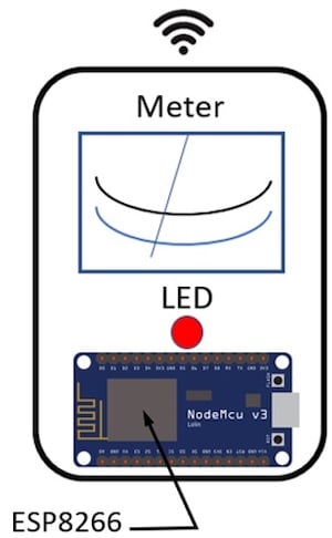
Figure 1. A basic Wi-Fi network scanner concept diagram.
In this hands-on project tutorial, you will learn the internal workings of the ESP8266 microcontroller and how you can build a simple Wi-Fi network scanner using only a few off-the-shelf electronic components.
Required Hardware
- ESP8266 Node MCU Development Board: U1
- 22Kilo-ohm (KΩ) (red, red, orange, gold stripes) resistor: R1
- 330ohm (Ω) (orange, orange, brown, gold stripes) resistor: R2
- Red LED: LED 1
- (2) 0 – 1mA analog panel meter: M1
- Solderless breadboard
- Jumper wires
Before discussing the project build, let’s quickly review the basics of ESP8266 microcontrollers.
The ESP8266 Microcontroller
The ESP8266 microcontroller, developed by Espressif Systems, is a 32-pin, quad-flat-no-lead (QFN) Wi-Fi system on a chip (SOC) package. It integrates a radio circuit consisting of antenna switches, a power amplifier, a low noise receiver amplifier, filters, a power management module, and an RF balun.
The RF balun is an electrical component capable of taking a balanced signal and converting it to an unbalanced signal. A balanced signal has equal line impedances. An unbalanced signal has unequal impedances. The RF balun ensures the antenna works properly with the RF transmitter and receiver circuits through the internal network switch.
At the heart of the ESP8266 is a 32-bit microprocessor manufactured by Tensilica. The Tensilica microprocessor manages the binary data and coding language information required to work with the ESP8266’s electrical interfaces. Such electrical interfaces include the general-purpose input/output (GPIO), the universal asynchronous receiver transmitter (UART), pulse width modulation (PWM), serial peripheral interface (SPI), and the analog to digital converter (ADC). With these electrical interfaces, the ESP8266 can be wired to external sensors, transistor driven actuators, discrete LEDs, and displays (LCD, OLED, and LED).
In addition, the ESP8266 microcontroller supports the Wi-Fi specification of 802.11 b/g/n and the 2.4 GHz operating frequency spectrum. Aside from supporting a variety of electrical interfaces, the small QFN Wi-Fi SoC microcontroller can be operated from a voltage supply range of 2.5V - 3.6V. The average operating current of the SoC microcontroller is 80 milliamperes (mA). Figure 2 illustrates the ESP8266 system block diagram (SBD) architecture.
Figure 2. The ESP8266 SBD architecture.
To aid in prototyping wireless sensor and control applications, the ESP8266 is packaged as a small PCB module or a dual in-line (DIL) development board.
Figure 3. Prototyping options for the ESP8266: PCB module and DIP development board.
As additional references, the circuit schematic diagram and pinout of the ESP8266 are provided in Figures 4 and 5.
Figure 4. The ESP8266 PCB module circuit schematic diagram.
Figure 5. The ESP8266 pinout.
With a basic understanding of the ESP8266, it’s time to build the network scanner!
Wiring the ESP82266 Wi-Fi Network Scanner Circuit
The Wi-Fi network scanner can receive wireless data from a nearby router and display its service set identifier (SSID) content data on a monitor. Such a device can be used as a troubleshooting tool to determine if the suspect router is transmitting a wireless signal.
The construction of the scanner is simple in design and only requires three main components: the ESP8266 Wi-Fi SoC microcontroller, an analog meter (ammeter), and an LED.
Figure 6. The ESP8266 Wi-Fi network scanner SBD.
The scanner initiates by running a basic MicroPython-based script on the ESP8266. Once the microcontroller receives a router’s SSID content data, the analog meter swings to a predetermined angle.
The analog ammeter’s movement is based on the amount of current flowing through its internal coil winding. A series limiting resistor is used to establish an adequate current flow for the analog meter’s needle movement. A discrete LED provides a secondary visual indicator.
You can build the Wi-Fi network scanner using the components listed at the beginning of this tutorial using the Fritzing-created electrical wiring diagram shown in Figure 7 to assist in the wiring. I recommend the use of a solderless breadboard for layout and placement of the components to ensure proper wiring of the circuit.
Figure 7. The ESP8266 WiFi Network Scanner electrical wiring diagram.
The LED orientation is very important to ensure it illuminates properly. Therefore, you need to place the optoelectronic component on the solderless breadboard as shown in Figure 7 to ensure proper operation.
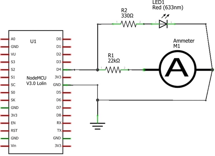
You can use an analog volt-ohm-milliammeter (VOM) as an appropriate substitute for the analog panel meter. Additionally, the circuit schematic diagram shown in Figure 8 can be used if you have experience in wiring electrical and electronic circuits on a solderless breadboard.
Figure 8. The ESP8266 WiFi Network Scanner circuit schematic diagram.
Here is an example of a Wi-Fi network scanner using a retro Radio Shack Science Fair 200 in One Electronic Project Lab.
Figure 9. A Retro Electronics based Radio Shack Science Fair ESP8266 WiFi Network Scanner.
You can code the scanner’s software using the MicroPython coding language. The scanner code is shown in Figure 10.
Figure 10. The Wi-Fi Network Scanner MicroPython Code.
Upload the code to the ESP8266’s RAM. Upon running the code, a nearby router’s SSID content data will immediately display on your development system’s monitor and the analog meter will swing to an appropriate reading level. Also, the onboard and external LEDs will illuminate simultaneously. As a coding challenge, modify the MicroPython code to allow you to log the SSID content data into a file.
Happy Wi-Fi scanning!