Build an ESP32-based dual NRF24L01 setup to study wireless communication and RF spectrum activity
Wireless communication powers everything from earbuds and smartwatches to home automation devices. Most of these gadgets rely on the crowded 2.4GHz ISM band, where Bluetooth, Wi-Fi, and several RF modules operate simultaneously. In this project, we will build an ESP32-based RF experimentation platform using two NRF24L01 + PA + LNA transceivers to better understand wireless signal behaviour, spectrum congestion, packet transmission, and frequency hopping concepts.
This project is intended strictly for educational research in a controlled environment using devices you own. The objective is to explore how wireless communication behaves under heavy RF activity and learn how multiple transceivers can be controlled simultaneously using the ESP32’s dual SPI interfaces.
The ESP32 acts as the central controller while two NRF24L01 modules operate independently through the HSPI and VSPI buses. By rapidly transmitting data packets across multiple channels, the setup demonstrates how crowded RF environments can affect nearby wireless communication systems.
What You Will Learn
This project is useful for anyone interested in embedded systems, RF communication, IoT development, or wireless security research. During the build, you will learn:
- How Bluetooth communication works in the 2.4GHz band
- The basics of Frequency Hopping Spread Spectrum (FHSS)
- How to interface multiple SPI devices with an ESP32
- NRF24L01 PA + LNA module operation
- RF power stability and decoupling techniques
- Dual SPI communication using HSPI and VSPI
- Practical hardware assembly and firmware flashing
Understanding Bluetooth Communication
Bluetooth is one of the most widely used short-range wireless communication protocols. It operates in the 2.4GHz ISM band and enables devices such as smartphones, headphones, wearables, and smart home products to communicate wirelessly.
Modern Bluetooth systems use a method called Frequency Hopping Spread Spectrum, commonly known as FHSS. Instead of staying on a single frequency, Bluetooth devices rapidly switch between channels thousands of times per second. This hopping technique improves reliability and reduces interference from other devices sharing the same spectrum.
Bluetooth Classic typically uses 79 channels, while Bluetooth Low Energy (BLE) uses 40 channels with adaptive hopping algorithms optimised for low-power devices.
Because many wireless technologies share the 2.4 GHz spectrum, understanding how RF congestion affects communication is an important part of wireless engineering.
Why Use Two NRF24L01 Modules?
A single NRF24L01 transceiver can operate on one channel at a time. Although it can switch channels quickly, coverage gaps still exist during transmission.
Using two NRF24L01 modules allows the ESP32 to communicate with both transceivers simultaneously through independent SPI buses. This creates wider spectrum activity and improves experimental coverage across multiple channels.
The PA + LNA versions of the NRF24L01 are particularly useful because they include:
- A Power Amplifier (PA) for stronger transmission output
- A Low Noise Amplifier (LNA) for improved signal reception sensitivity
This configuration provides a better platform for studying RF behaviour in dense wireless environments.
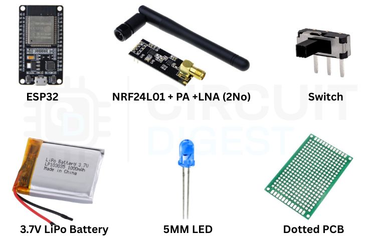
Components Required
To build this project, you will need:
- ESP32 development board
- 2 × NRF24L01 + PA + LNA modules
- 3.7V LiPo battery or USB power bank
- Toggle switch
- 5mm LED
- 220Ω resistor
- 10µF capacitors for NRF24L01 power stabilization
- Perfboard or custom PCB
- Jumper wires and headers
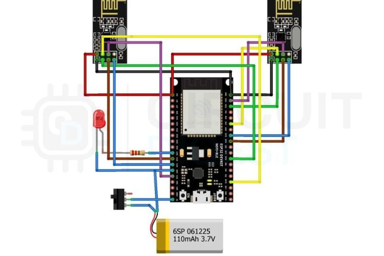
Circuit Overview
The two NRF24L01 modules are connected to separate SPI buses on the ESP32:
Left NRF24L01 (HSPI)
- CE → GPIO 16
- CSN → GPIO 15
- SCK → GPIO 14
- MOSI → GPIO 13
- MISO → GPIO 12
Right NRF24L01 (VSPI)
- CE → GPIO 22
- CSN → GPIO 21
- SCK → GPIO 18
- MOSI → GPIO 23
- MISO → GPIO 19
Both modules operate at 3.3V. A 10µF capacitor should be connected across the VCC and GND pins of each NRF24L01 module to stabilise power delivery and prevent brownout issues during transmission bursts.
An LED connected to GPIO 27 through a 220Ω resistor acts as a status indicator.
The entire setup can be powered using a LiPo battery connected to the ESP32 VIN pin or through the USB connector using a power bank.
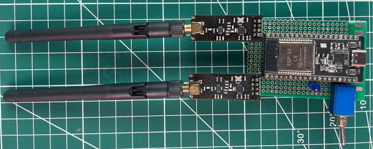
Hardware Assembly
Begin by mounting the ESP32 and both NRF24L01 modules onto a perfboard. Keep the RF modules separated slightly to reduce self-interference and ensure stable antenna performance.
Carefully solder all SPI connections and verify the power rails before turning on the system. Since PA + LNA modules draw higher current than standard NRF24L01 boards, stable power delivery is critical.
If you experience unreliable module initialisation, random resets, or weak transmission behaviour, the issue is often related to insufficient current or poor decoupling.
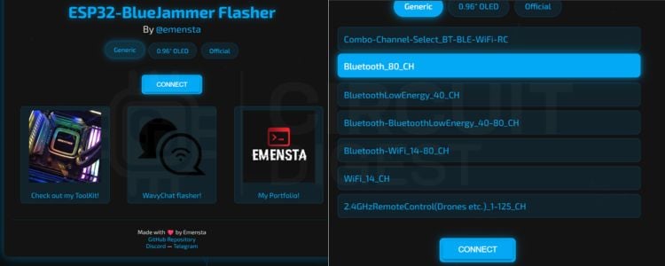
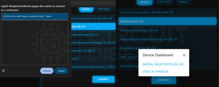
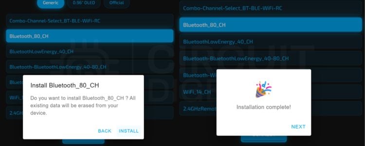
Firmware and Operation
The firmware initialises both SPI buses independently and configures each NRF24L01 module for rapid channel activity across the 2.4GHz band.
Once powered, the ESP32 continuously controls both RF modules simultaneously. This setup creates an excellent experimental platform for observing how crowded-spectrum conditions can influence wireless communication reliability.
Because the ESP32 supports multiple hardware SPI interfaces, both transceivers can operate in parallel without significant timing conflicts.
Understanding HSPI and VSPI on the ESP32
One of the most useful features of the ESP32 is its dual hardware SPI architecture. Unlike many microcontrollers that provide only one SPI interface, the ESP32 includes independent HSPI and VSPI peripherals.
This allows multiple high-speed SPI devices to run simultaneously with separate communication lines.
In this project:
- HSPI controls the first NRF24L01 module
- VSPI controls the second NRF24L01 module
This arrangement increases channel coverage and improves overall RF experimentation capability.
Common Troubleshooting Tips
If one of the NRF24L01 modules fails to initialise:
- Check all SPI connections carefully
- Verify the module is receiving stable 3.3V power
- Add or replace the 10µF decoupling capacitor
- Confirm the correct CE and CSN pin assignments in the firmware
If the ESP32 restarts unexpectedly:
- Use a higher current power source
- Avoid powering PA + LNA modules directly from weak USB adapters
- Ensure the battery or regulator can handle peak current demands
If communication behaviour appears inconsistent:
- Recheck solder joints
- Keep antenna modules away from metal surfaces
- Minimise wire lengths where possible
Expanding the Project
This platform can be extended into several advanced RF learning applications, including:
- Wireless packet analysis
- NRF24L01 communication networks
- Custom sensor nodes
- RF scanning experiments
- ESP32 wireless debugging tools
- IoT communication testing
You can also design a custom PCB enclosure to make the project more compact and portable.
Final Thoughts
This ESP32 Bluetooth Jammer project is an excellent way to explore wireless communication fundamentals and learn how RF systems behave in busy spectrum environments. By combining two high-power transceivers with the ESP32’s dual SPI capability, you can gain practical experience with embedded wireless development and RF experimentation.
ESP32 Projects like this help bridge the gap between theoretical networking concepts and real-world wireless behaviour, making them especially valuable for students, makers, and embedded engineers interested in RF technologies.
This project should always be used responsibly and only inside controlled environments for educational experimentation and research.