Maker Pro
Maker Pro

Short pulse output

bigkim100

Apr 17, 2013
270
Joined
Apr 17, 2013
Messages
270
Is it possible to have a circuit that will output a 2 second pulse no matter what duration a button is pressed?
Output switching is to a relay, operating voltage is unimportant, as I will build to whatever your requirements are(eg:3,5,6,9,12vdc).
Thanks in advance
 

dragon

Oct 31, 2022
248
Joined
Oct 31, 2022
Messages
248
if you short to a cap, and fill it up in a microsecond, that leaks out to another cap slowly that might do it.
 

bigkim100

Apr 17, 2013
270
Joined
Apr 17, 2013
Messages
270
would that not just continue to charge the Capacitor the entire time the button is pressed?
 

danadak

Feb 19, 2021
781
Joined
Feb 19, 2021
Messages
781
Yes, use ATTINY85, and mBlock to program it. Here is solution :

1670336533944.png

mBlock is free, use a Arduino Nano board 9$3) to program the ATINY85. mBlock takes your block
configuration and generates Arduino code then using Nano as a programmer programs the
ATTINY85 chip. Or just use the Arduino Nano board. When suing the ATTINY85 accuracy is ~5%
for pulse width, Nano board < .1% error. If button bounces a lot easy to add delay code to wait until
its fully on stable and fully off stable. So no false triggers.

if you need alarm tone and/or flasing alarm LED easy to add that.

This is breadboard, uses a transistor to drive a load like a relay or high power LED or....whatever

1670336313266.png

Regards, Dana.
 
Last edited:

dragon

Oct 31, 2022
248
Joined
Oct 31, 2022
Messages
248
would that not just continue to charge the Capacitor the entire time the button is pressed?
if you charge two capacitors, one will block when the other discharges, then u can make it discharge on release of the button only.
 

kellys_eye

Jun 25, 2010
6,514
Joined
Jun 25, 2010
Messages
6,514
Is it possible to have a circuit that will output a 2 second pulse no matter what duration a button is pressed?
It's called a one-shot (monostable) circuit. You can get the pulse output to start at button press or button release depending on what way you want to trigger it (rising edge or falling edge). Look at the datasheet for the HFC4047 (single monostable) or 4098 (dual monostable) or even the ubiquitous NE555 for which there are dozens of examples all over t'internet.

PS - Ignore advice from user called 'Dragon'.....
 

AnalogKid

Jun 10, 2015
2,913
Joined
Jun 10, 2015
Messages
2,913
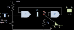
Here is an innergoogle-grab of a classic NAND-gate monostable. A negative-going edge at the input (either a switch closure or the negative edge of an input pulse signal) causes a negative-going pulse at the output. In this circuit, the output pulse width is independent of the input signal after a negative-going edge triggers it. The input can stay low, go high, bounce up and down; whatever. After the output signal times out, the next negative-going input edge will trigger the circuit again.


If you change both gates to NOR gates, then a positive edge at the input produces a positive-going pulse at the output.

Note that the monostable circuit in the 555 datasheet is not a true monostable. If the Trigger signal is held low longer than the output pulse period, the output pulse will stay high

ak

1670344207319.png
 
Last edited:

danadak

Feb 19, 2021
781
Joined
Feb 19, 2021
Messages
781
The problem with simple cmos gate oscillators or 555 timer is accuracy
of pulse width and T & V effects. If you dont care about fact electrolytic
caps have wide tolerance range or variations (without pot trimming) of
50+ % then use those. Notice the tolerance column in this selector tool :


115,000+ capacitors all with those crappy tolerances.......

And not to ignore add on to this variation in cmos of gate threshold wide
range device to device, in case your design is not a one-off.

Otherwise use ones where IC is trimmed in production to give you accurate
results, like todays processors and their onchip clocks. Or even better the
Nano type of board where an xtal determines timing accuracy.

Lastly processors have better control over power on glitches, eg. proper design
will have none of those unwanted unpredictable pulses on their outputs when
power is ramping up or down.

Again processors have largely eliminated that problem.'


Regards Dana.
 

kellys_eye

Jun 25, 2010
6,514
Joined
Jun 25, 2010
Messages
6,514
I get the impression that the difference between 1.99 seconds and 2.01 seconds would be irrelevant. Using a sledgehammer to crack a nut isn't always the right way.
 

danadak

Feb 19, 2021
781
Joined
Feb 19, 2021
Messages
781
I get the impression that the difference between 2 seconds and 1 or 3 seconds would be relevant.
Especially since OP has stipulated the 2 sec pulse width he wants. Using the right part for the job is
always the right way. For all we know he may need a +/- 5 ppm pulse, even my solution would be
inadequate.

And just a guess, the Intel or ARM or Freescale guys probably dont think of a ATTINY85 as a hammer...
let alone a sledge hammer.

And most of these CMOS logic timing designs hang large caps directly off pins, and CMOS manufacturers tell
us thats a NO-NO.

Just a thought, you might check into the fact CMOS logic not built in todays processor geometries, point in fact
a low end processor might just take less die area than a CMOS logic type device. Just a thought.

Lastly we do not know if there are any safety factors involved, like power up transients creating
unwanted pulses. A partsy solution if discrete logic and discretes used to prevent it. Just one more
capability on many of the newer processors.


Regards, Dana.
 
Last edited:

dragon

Oct 31, 2022
248
Joined
Oct 31, 2022
Messages
248
here I did a bit of work in falstad, its not quite right, but im too tired... :(
 

Harald Kapp

Moderator
Moderator
Nov 17, 2011
13,758
Joined
Nov 17, 2011
Messages
13,758
its not quite right
Why post it then?
but im too tired...
And this is reason enough to leave it up to us to make teh best of it?

Your circuits never show clearly identifiable input or outut signals. How do you think we can folllow along without that essential information?
Some of your circuits have been rated as non-operational by several members of this forum. You haven't shown any evidence of a real working circuit (not a simulation) despite your announcements.
 

dragon

Oct 31, 2022
248
Joined
Oct 31, 2022
Messages
248
here i fixed it with a diode, its working now, adjust r and c on the end capacitor for different time durations of the pulse.
 

Harald Kapp

Moderator
Moderator
Nov 17, 2011
13,758
Joined
Nov 17, 2011
Messages
13,758
I still have no ide where the output is. Plus: what is the signal waveform at the output?
And again you use a 100 nΩ resistor which is completely unrealistic. In a real circuit the resistance of the wiring will be a lot more.
 

dragon

Oct 31, 2022
248
Joined
Oct 31, 2022
Messages
248
the 100nanoohm resistor just stands for a short (Just a wire.) Falstad makes u put them in for some reason, it doesnt work without them in the simulation.

The output is the little box on the right, and the current pulse is inside that, you connect that up to your load.
The waveform is a capacitor discharge pulse, this circuit just runs on dc.
 

Harald Kapp

Moderator
Moderator
Nov 17, 2011
13,758
Joined
Nov 17, 2011
Messages
13,758
The output is the little box on the right,
By "little box" do you mean the 1 k resistor? It is not helpful not to use the correct names of components.
The waveform is a capacitor discharge pulse,
add 1: please show the waveform which is still missing (or at least I am missing it).
add 2: a capacitor discharge waveform, while technically being a pulse, is not useful for switching a relay as requested by the op. Therefore your circuit is not useful to the op.

I suggest you rad and learn about active components like transistors, operational amplifier, logic gates etc. I guarantee that your idea of doing everything passively will not work out. It is against the collective experience and knowledge of hundreds of thousands, if not millions, of electronics engineers.
Also do not rely heavily on simulations. Simulators always use mathematical models of real components, tehreby neglecting or idealizing some real world effects. It it simulates, it doesn't necessarily mean it will run in the real world. And vice versa. Go ahead, build and test some of the circuits you proposed here and verify the real wolrd behavior vs. the simulation.
 

dragon

Oct 31, 2022
248
Joined
Oct 31, 2022
Messages
248
A cap pulse can switch a relay on! its still power, its just a matter of supplying the right amount of energy it needs to not disconnect/turn off, for 2 seconds. (so take into account a little rms, it has to be a bit longer duration.)

I am going to start building circuits soon, I have to go off to the components shop, probably do it on friday. (A couple of days.) Cause I have to wait for another 50 bucks, then ill have 120 to spend, then I do everything discrete.

I am actually very confident and very happy that everything is going to work! I am on cloud 9 actually, very pleased with myself.


<edit ill get the oscilloscope view on next>
 
Last edited:

bigkim100

Apr 17, 2013
270
Joined
Apr 17, 2013
Messages
270
It's called a one-shot (monostable) circuit. You can get the pulse output to start at button press or button release depending on what way you want to trigger it (rising edge or falling edge). Look at the datasheet for the HFC4047 (single monostable) or 4098 (dual monostable) or even the ubiquitous NE555 for which there are dozens of examples all over t'internet.

PS - Ignore advice from user called 'Dragon'.....
Will the 555 not still continue the pulse output if the it is triggered past the duration of its timing cycle??

I get the impression that the difference between 1.99 seconds and 2.01 seconds would be irrelevant. Using a sledgehammer to crack a nut isn't always the right way.
You are quite correct, as per usual, Sir

Here is an innergoogle-grab of a classic NAND-gate monostable. A negative-going edge at the input (either a switch closure or the negative edge of an input pulse signal) causes a negative-going pulse at the output. In this circuit, the output pulse width is independent of the input signal after a negative-going edge triggers it. The input can stay low, go high, bounce up and down; whatever. After the output signal times out, the next negative-going input edge will trigger the circuit again.


If you change both gates to NOR gates, then a positive edge at the input produces a positive-going pulse at the output.

Note that the monostable circuit in the 555 datasheet is not a true monostable. If the Trigger signal is held low longer than the output pulse period, the output pulse will stay high

ak

View attachment 57226
Thank you very much analogue kid. As per usual, your work is excellent. Can you complete the circuit for me, with a relay output (maybe a transistor to drive it) for my own knowledge

I get the impression that the difference between 1.99 seconds and 2.01 seconds would be irrelevant. Using a sledgehammer to crack a nut isn't always the right way.
You are quite correct sir

It's called a one-shot (monostable) circuit. You can get the pulse output to start at button press or button release depending on what way you want to trigger it (rising edge or falling edge). Look at the datasheet for the HFC4047 (single monostable) or 4098 (dual monostable) or even the ubiquitous NE555 for which there are dozens of examples all over t'internet.

PS - Ignore advice from user called 'Dragon'.....
Is it not the case that if the Trigger signal is held low longer than the output pulse period, the output pulse will stay high

Just to add to the spec's, I can handle and resolve any glitchyness in regards to power up, etc (I think). The circuit tolerance's are not that picky.
 

hevans1944

Hop - AC8NS
Jun 21, 2012
4,889
Joined
Jun 21, 2012
Messages
4,889
@danadak is absolutely right: integrated circuit processors are not sledge hammers, and they are really "dirt cheap" solutions to timing longish periods that in the previous century (circa 1970 or earlier) would have had to have been an analog circuit.

Way back then, you could have cobbled together something digital with TTL (transistor-transistor-logic) iintegrated circuiits, but a "simple" RC circuit followed by a threshold detector (or analog comparator) and a few transistors solved many timing problems with delays on the order of a few minutes to a few hours without resorting to electrolytic capacitors and meg-ohm resistors. Consider that a six- or eight-pin PIC costing a few pennies will do the job with only a few lines of programming.
 
Top