Maker Pro
Maker Pro

2-stage Class A Amplifier: Gains(voltage and power)

Mark Malolot

Nov 1, 2015
16
Joined
Nov 1, 2015
Messages
16
You have to start by drawing the circuit and showing the load and if the two stages are directly coupled or capacitor coupled.
My output should be like this sir, dont mind the values i just copy-paste it with the first amp.
 

Attachments

  • 1.png
    1.png
    17.1 KB · Views: 67

CDRIVE

Hauling 10' pipe on a Trek Shift3
May 8, 2012
4,960
Joined
May 8, 2012
Messages
4,960
OK, you're using spice software. We can work with that.

There are a number of issues with your component values but we can't correct them for you. We can steer you in the direction of solution though.
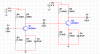
The first thing you need to do is connect a Vcc source. Then have to recalculate your resistor values. Your collector resistor is lower than it needs to be and your bias resistors are too low too. That transistor is saturated. When you're done with recalculating the resistors you can then do the same with the two coupling caps. They're capacitance is too low also.

BTW... I kinda like Sir Chris. :D

Chris
 

Mark Malolot

Nov 1, 2015
16
Joined
Nov 1, 2015
Messages
16
Ahaha Sir Chris :) Anyways thanks a lot. oh? okay thanks a lot Sir. So the values should be bigger then. Is my supply satisfactory for an amp? My Ic here is 10 millliamps, is it way too big?
 

Mark Malolot

Nov 1, 2015
16
Joined
Nov 1, 2015
Messages
16
My instructor didn't discuss with me the filters, i learned through internet this so called high pass and low pass filters yet i don't have a good grasp about it. Can you at least share with me which is the high pass and low pass filter in my design Sir Chris @CDRIVE
 

Martaine2005

May 12, 2015
4,956
Joined
May 12, 2015
Messages
4,956
Sir Martin :p has given you good advice but I'm curious.. You didn't state what your input source or output load will be. Did your instructor specify these?
He didn't need to.
I got Patuleas' protoype working!:D

Martin
 

Mark Malolot

Nov 1, 2015
16
Joined
Nov 1, 2015
Messages
16
@dorke Yes sir, it is a great video indeed. Thats why im very much thankful to him :) As well as everyone who spend time helping me out :D
 

GPG

Sep 18, 2015
452
Joined
Sep 18, 2015
Messages
452
Since the load is the input of an opamp the gain could be made much higher by setting the current lower and Re lower and Rc higher and biasing accordingly. The optimum for low noise depends on the input impedance
http://datasheet.eeworld.com.cn/pdf/272577_SECOS_2N2222A.html
Starting by setting the current to 1mA (good for low impedance source) and DC degeneration emitter resistance to 1K (1V of degen)
Leaves (5v supply) 4V to split across the transistor and Rc. So Rc = 2V/1mA ~2.2K And Vb = 1+.6(Vbe) V and Ib ~ Ie/100(assumed Beta) Make the base bias bleed resistances current 10X of this Gives 33k(upper) 15K(lower) AC bypass on Re of course. Gain can be controlled by adding a resistor in series with the bypass cap.
 
Top