Maker Pro
Maker Pro

Basic Announciator

nailtherail

Apr 17, 2023
6
Joined
Apr 17, 2023
Messages
6
I have a 12v circuit which is mainly logic based, with the odd switch, to create a desired output which lights a specified number on different LED seven segment displays.
There is nothing to stop the push button shown being pushed multiple times, or even how long the push button is pressed each time. Each time the button is pressed, it restarts the timer to a 3 minute countdown.

However, I am hoping to be able to add a basic audible sound (to announce the initial button press event occurring) of about one second via a bell or buzzer, which only sounds when the push button is INITIALLY pushed and then should not trigger again until the output of the 3 minute timer resets itself again (Back to 0v).
I have included a basic schematic of the current circuits design with the purple showing possible sounder circuit path.

Can anybody recommend the best way to achieve the above??

It was my aim to get the sounder to possibly sound once if the switch was in position '1', twice in position '2' and three time in position '3' but I think this is probably too complicated!! (unless you know and can suggest a way otherwise)
 

Attachments

  • basic announce.jpg
    basic announce.jpg
    33.2 KB · Views: 7

AnalogKid

Jun 10, 2015
2,925
Joined
Jun 10, 2015
Messages
2,925
It sounds like what you want to do is add a 1 second monostable to the output of the 3 minute timer. The output of this monostable drives the beeper. Because the 3 minute timer is stable for much linger than 1 second, you can get away with a "boxcar" circuit, basically a differentiator, that turns the leading edge out of the 3 minute timer into a short pulse.

You show all AND gates. If so, the output of the 3-minute timer is a positive-going edge. Depending on how much current the timer output can supply, you might be b=able to get away with simply connecting the beeper to the timer output with a large capacitor. If the timer output cannot make enough current, you will need a 1-transistor driver for the beeper.

Please post a schematic of the 3-mintue timer circuit, with component part numbers and a reference designators for each component.

And - making the circuit beep a different number of times for each switch position is a bit more complex. Where are you located?

ak
 

Bluejets

Oct 5, 2014
7,054
Joined
Oct 5, 2014
Messages
7,054
Lack of any switch debounce could also present a problem in the current circuit.
 

AnalogKid

Jun 10, 2015
2,925
Joined
Jun 10, 2015
Messages
2,925
Each time the button is pressed, it restarts the timer to a 3 minute countdown.
This sounds like a retriggerable monostable. A little switch bounce fur at the end of its input signal is not going to have a large effect on a 3 minute period.

ak
 

Bluejets

Oct 5, 2014
7,054
Joined
Oct 5, 2014
Messages
7,054
And then there is the 3 position switch with floating pins....
 

AnalogKid

Jun 10, 2015
2,925
Joined
Jun 10, 2015
Messages
2,925
And then there is the 3 position switch with floating pins....
True, the circuit as shown needs work, but it might me more of a concept drawing than an actual schematic. Still waiting on a TS response.

ak
 

danadak

Feb 19, 2021
797
Joined
Feb 19, 2021
Messages
797
Is the numeric written to 7 seg display held when next display is updated ?

What is the value of the numeric represent ? What generates its value ?

This whole design cries out for a simple processor solution, like Arduino.
And use block language on it, an example you can look at :


Debouncing the switch easy to add in the blocks code.....


Regards, Dana.
 

nailtherail

Apr 17, 2023
6
Joined
Apr 17, 2023
Messages
6
Is the numeric written to 7 seg display held when next display is updated ?

What is the value of the numeric represent ? What generates its value ?

This whole design cries out for a simple processor solution, like Arduino.
And use block language on it, an example you can look at :


Debouncing the switch easy to add in the blocks code.....


Regards, Dana.


The circuit shown was merely a basic design to show how it is set up, there are also transistors to switch drive the LED's with resistors but these I didn't realise would be necessary to show to try to keep things simple for the design of what already exists.
There is also resistors to stop the switches from floating, again not shown as I wanted to keep things simple.
 

nailtherail

Apr 17, 2023
6
Joined
Apr 17, 2023
Messages
6
True, the circuit as shown needs work, but it might me more of a concept drawing than an actual schematic. Still waiting on a TS response.

ak
The circuit shown was merely a basic concept design to show how it is set up, there are also transistors to switch drive the LED's with resistors but these I didn't realise would be necessary to show to try to keep things simple for the design of what already exists.
There is also resistors to stop the switches from floating, again not shown as I wanted to keep things simple. The timer is a pre-purchased timer circuit with a +ve, -ve, trigger, output connectors.
 

nailtherail

Apr 17, 2023
6
Joined
Apr 17, 2023
Messages
6
It sounds like what you want to do is add a 1 second monostable to the output of the 3 minute timer. The output of this monostable drives the beeper. Because the 3 minute timer is stable for much linger than 1 second, you can get away with a "boxcar" circuit, basically a differentiator, that turns the leading edge out of the 3 minute timer into a short pulse.

You show all AND gates. If so, the output of the 3-minute timer is a positive-going edge. Depending on how much current the timer output can supply, you might be b=able to get away with simply connecting the beeper to the timer output with a large capacitor. If the timer output cannot make enough current, you will need a 1-transistor driver for the beeper.

Please post a schematic of the 3-mintue timer circuit, with component part numbers and a reference designators for each component.

And - making the circuit beep a different number of times for each switch position is a bit more complex. Where are you located?

ak
Hi, I thought it probably was a bit to complex to get a different number of buzzes depending on which switch triggers the timer initially. will probably just stick with a one second sound no matter which switch has been activated. The clarify this is just a basic concept circuit to show how it is set up, there are also transistors to switch drive the LED's with resistors but these I didn't realise would be necessary to show to try to keep things simple for the design of what already exists.
There is also resistors to stop the switches from floating, again not shown as I wanted to keep things simple.
 

AnalogKid

Jun 10, 2015
2,925
Joined
Jun 10, 2015
Messages
2,925
Leaving out parts to reduce clutter, improve clarity, and focus on the unknown parts of a circuit is fine, as long as you state what you are doing so we all don't jump on what look like newbie mistakes.

It sounds like what you want to do is add a 1 second monostable to the output of the 3 minute timer. The output of this monostable drives the beeper. Because the 3 minute timer is stable for much longer than 1 second, you can get away with a "boxcar" circuit, basically a differentiator, that turns the leading edge out of the 3 minute timer into a short pulse.

Is this part correct? The one-second beeper monostable is triggered by the leading edge of the output of the three minute timer.

If yes, then have you determined how you want to implement the three minute timer? That's a long time for a simple R-C timer such as a 555. A better, more stable choice might be using a counter such as the CD4060. This is a very common solution for medium-to-long range timers.

ak
 

nailtherail

Apr 17, 2023
6
Joined
Apr 17, 2023
Messages
6
Leaving out parts to reduce clutter, improve clarity, and focus on the unknown parts of a circuit is fine, as long as you state what you are doing so we all don't jump on what look like newbie mistakes.


Is this part correct? The one-second beeper monostable is triggered by the leading edge of the output of the three minute timer.

If yes, then have you determined how you want to implement the three minute timer? That's a long time for a simple R-C timer such as a 555. A better, more stable choice might be using a counter such as the CD4060. This is a very common solution for medium-to-long range timers.

ak

Yes, That sounds perfect, whatever needs to be triggered on the leading edge of the timer and not be able to be triggered again until the timer has timed out which could be anything from 3 minutes, to five minutes depending on when the time when the timer was last activated. What would the circuit look like, I have played around and cant get it to just activate on the initial, only on everytime the timer is activated?
 

nailtherail

Apr 17, 2023
6
Joined
Apr 17, 2023
Messages
6
Yes, That sounds perfect, whatever needs to be triggered on the leading edge of the timer and not be able to be triggered again until the timer has timed out which could be anything from 3 minutes, to five minutes depending on when the time when the timer was last activated. What would the circuit look like, I have played around and cant get it to just activate on the initial, only on everytime the timer is activated?

Leaving out parts to reduce clutter, improve clarity, and focus on the unknown parts of a circuit is fine, as long as you state what you are doing so we all don't jump on what look like newbie mistakes.


Is this part correct? The one-second beeper monostable is triggered by the leading edge of the output of the three minute timer.

If yes, then have you determined how you want to implement the three minute timer? That's a long time for a simple R-C timer such as a 555. A better, more stable choice might be using a counter such as the CD4060. This is a very common solution for medium-to-long range timers.

ak

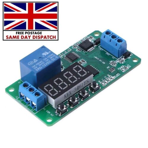
You asked what the 3 minute timer circuit was that is being used. I have finally found the circuit which was purchased from ebay:
This circuit allowed a variable time to be set
 
Top