Maker Pro
Maker Pro

Brushless motor controller

am.steen

Jul 10, 2023
41
Joined
Jul 10, 2023
Messages
41
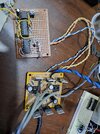
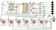
I want to Build this circuit for brushless motor
1698686873185.png
But my motor is 220v so I get Another mosfet no. IRF740 that has 400v and the IR2104 can have 600v
So what I should change also to drive 220v motor ??
I get this circuit from this link:

I did not built the circuit yet as I need to know precautions before start.
 

Bluejets

Oct 5, 2014
7,057
Joined
Oct 5, 2014
Messages
7,057
The fact that the motor is high voltage rating not enough for you...???
Plenty of motors from RC gear which operate at a safe level.
Suggest you give that some thought.
 

am.steen

Jul 10, 2023
41
Joined
Jul 10, 2023
Messages
41
In fact I have a device that depends on this motor to work but it's control board is damaged so I want to build this circuit to run the device again it was working on 220v dc and draw 8A
 

Attachments

  • 20231003_194342.jpg
    20231003_194342.jpg
    231.3 KB · Views: 7

am.steen

Jul 10, 2023
41
Joined
Jul 10, 2023
Messages
41
The problem here is the ground it is common for mosfet , IC's and ardinuo
If we use 220v it will burn ardinuo ?? How to modify the circuit ??
 

kellys_eye

Jun 25, 2010
6,514
Joined
Jun 25, 2010
Messages
6,514
If we use 220v it will burn ardinuo ??
No, it won't.

Connect the IR2101 to a separate 12V source and increase the value of the resistors such that the developed voltage doesn't exceed the input rating of the Arduino (around 560k - may need adjustment).

All supplies (Arduino, 12V to IR2101 and the 220V DC supply) should have their 'negative' (i.e. ground) connections commoned.
 

kellys_eye

Jun 25, 2010
6,514
Joined
Jun 25, 2010
Messages
6,514
What is the function of 33k and 10k resistors ??
They are a voltage divider to (in the original schematic) reduce the 12V phase signals from each motor phase to a voltage level the Arduino can accept (3.3V). The Arduino uses these voltages phase feedback signals to monitor and control the motor speed.

Since your plan is to drive the motor with 220VDC then the phase signals will be correspondingly larger and therefore the voltage divider will have to be adjusted to compensate for that.
 

am.steen

Jul 10, 2023
41
Joined
Jul 10, 2023
Messages
41
Ok I design another circuit without feedback and I built it

This is the circuit
1698940331299.png


I connect the DC 220v Power through a serial 220v LAMP to be safe in case of short circuit.
When apply 12v to circuit I get short circuit across 220V and the lamp light.
I disconnect The DC 220V and test the +VE and GND of 220v Input and I found the they becomes short when we apply the 12v on IC IR2104 and when disconnect 12v they becomes open.

How this comes ??
 

kellys_eye

Jun 25, 2010
6,514
Joined
Jun 25, 2010
Messages
6,514
You don't show a common ground connection from the Arduino. The Arduino 0V line must be connected to the common 0V of the +12V and +220V DC supplies.
 

am.steen

Jul 10, 2023
41
Joined
Jul 10, 2023
Messages
41
Sorry I draw this schematic in short time but in the circuit I built the common ground is connected to all ic's and arduino also 12v is connected to all three ic's
 

kellys_eye

Jun 25, 2010
6,514
Joined
Jun 25, 2010
Messages
6,514
Without knowing your coding you will have to check the IN and /SD pin status to establish if any drive signal is being held high.
 

am.steen

Jul 10, 2023
41
Joined
Jul 10, 2023
Messages
41
I built Another simple circuit without any coding for testing the motor
1699630370259.png

When I try this circuit with BLDC 12v DC separate source the motor rotates Fine but very slow ( as it is 230V ) and I could change speed with the variable resistor then I try it on 220v DC separate source it rotates half circle and all IC's is burned then stops.
What I do wrong??
 

Attachments

  • 1699629194956.png
    1699629194956.png
    249 KB · Views: 2
Last edited:

Delta Prime

Jul 29, 2020
2,137
Joined
Jul 29, 2020
Messages
2,137
I built Another simple circuit without any coding for testing the motor
View attachment 61491

When I try this circuit with BLDC 12v DC separate source the motor rotates Fine but very slow ( as it is 230V ) and I could change speed with the variable resistor then I try it on 220v DC separate source it rotates half circle and all IC's is burned then stops.
What I do wrong??
Can you please take a photo? :)
 

am.steen

Jul 10, 2023
41
Joined
Jul 10, 2023
Messages
41
First board have the control ic and second board for mosfets other components on it it not connected except resistors
 

Attachments

  • 20231110_201434.jpg
    20231110_201434.jpg
    499 KB · Views: 3

bertus

Moderator
Nov 8, 2019
3,382
Joined
Nov 8, 2019
Messages
3,382
Hello,

The circuit in post #12 will not work with 220 Volts.
The gate voltage will be to high and burn the gate and distroy the "driver".
As you said the chips will be gone.

Use proper driver chips as in your earlier posts.

Bertus
 

am.steen

Jul 10, 2023
41
Joined
Jul 10, 2023
Messages
41
Should not mosfet gates be isolated from D-S 220v voltage ??
Do you mean I have to use driver ic between 4069 ic output and mosfet gates ?? Can you suggest an driver ic no. ??
 
Top