Hi all,
I have attached a circuit diagram from a car key transponder emulator that my friend has.
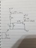
I believe these work by putting the key emulator in an energised electromagnetic field, the inductor from the field mutually couples to the LC tank circuit (as in the diagram).
I am not too familiar with the schematic, it seems the PNP is driven to provide 3V to the LC circuit from a Microcontroller pin, this will energise the LC circuit to produce oscillations and interact with the ignition coil, the output is taken from the 10K into the microcontroller.
Is this a Armstrong Oscillator circuit?
Does anyone know how this will interact and authenticate with the car?
Any help would be appreciated
Thanks in advance.
I have attached a circuit diagram from a car key transponder emulator that my friend has.
I believe these work by putting the key emulator in an energised electromagnetic field, the inductor from the field mutually couples to the LC tank circuit (as in the diagram).
I am not too familiar with the schematic, it seems the PNP is driven to provide 3V to the LC circuit from a Microcontroller pin, this will energise the LC circuit to produce oscillations and interact with the ignition coil, the output is taken from the 10K into the microcontroller.
Is this a Armstrong Oscillator circuit?
Does anyone know how this will interact and authenticate with the car?
Any help would be appreciated
Thanks in advance.