Maker Pro
Maker Pro

Decade counter to Momentary relay?

Stage_lighting_guy

Apr 13, 2023
4
Joined
Apr 13, 2023
Messages
4
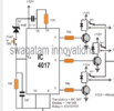
Full story, Im using a Decade counter to switch relays, 5V, I need the relays to be momentary. I understand that putting a Cap in the circuit to charge then stop the current flow when charged will achieve this. This is controlled by transistor before the relay. Is it better to stop current to the transistor or the switched current at the relay?
The cap needs to be discharged ready for the next cycle of the counter.

Thanks
 

AnalogKid

Jun 10, 2015
2,925
Joined
Jun 10, 2015
Messages
2,925
The cap will be smaller if you use it to modify the transistor's base current. That is, *before* the transistor. The transistor will turn on more slowly, causing more internal heating. this may or may not be an issue, depending on the power levels involved, the transistor/s package, etc.

Circuit operating voltage - ?

Relay operating voltage (not always the same thing, such as a 5 v circuit controlling a 24 v relay) - ?

Part number of the decade counter chip - ?

Time delay between operations - ?

ak
 

Stage_lighting_guy

Apr 13, 2023
4
Joined
Apr 13, 2023
Messages
4
My application is using a USB keyboard matrix PCB to simulate predetermined keystrokes controlled by footswitch , single push walks through the predetermined keys. All powered by USB 5v I hope
Chip 4017
Momentary contact= to typical key push
Full 10 cycles so may be rapid change but 10 cycle separation.
My thoughts counter out to 10k resistor to base of Transistor, Collector to one leg of relay control line, emitter to GND.

Where should the cap and a bleed off resistor come in the chain, between resistor and Base? Bleed off resistor bwteen cap and Base to GND?
 

Stage_lighting_guy

Apr 13, 2023
4
Joined
Apr 13, 2023
Messages
4
Not sure how to attach schematic. This is one i got from the Internet that I know works with the relay. I want to convert the relay to momentary contact. I know that at cap in series with the transistor base will work but not sure where to insert it and resistor required to discharge the cap after the counter has moved to the next output.
 

Attachments

  • Picture1.png
    Picture1.png
    120.1 KB · Views: 8

Stage_lighting_guy

Apr 13, 2023
4
Joined
Apr 13, 2023
Messages
4
i will be using more relays than the 3 shown in the diagram. Do I put the cap on the output of the counter before the 10k res. or after the res. Will a resistor to ground on the input side of the cap do the trick or is there more to it.

Thanks
 

crutschow

May 7, 2021
861
Joined
May 7, 2021
Messages
861
Here is one approach:
You select the capacitor size to get the momentary on-time you want.
D1 is to allow rapid discharge of the capacitor for the next pulse.
If you don't need fast recovery between pulses, then you could change D1 to a resistor (the resistor, of course, will reduce the on-time for a given capacitor value.

1682007785887.png
 

danadak

Feb 19, 2021
797
Joined
Feb 19, 2021
Messages
797
The problem with the C approach is possible relay chatter when the cap decays
and passes thru relay holding current minimum. And the button that advances the
4017 not being debounced. And you have power on issues / glitches that can occur.

A simple approach use an Arduino Nano (~ $3) and mBlock to program it.

Here is a solution I think would work to take care of those issues :

1682025047394.png


Mblock takes your code user configured blocks (the middle window) and turns it into Arduino code which
allows you to program the code into Arduino low end board. Board will drive transistors, and runs off USB
power if you choose to power it that way.

Lots of fun, easy to program, videos on doing this. Use by 6'th graders and on to program robots.

I labeled blocks with comments so you can see what its doing.

1682025573872.png


Regards, Dana.

PS : I have an error in the subroutine, it should look like -

1682030195158.png

Regards, Dana.
 
Last edited:

danadak

Feb 19, 2021
797
Joined
Feb 19, 2021
Messages
797
Your relay drive circuit should look like this :

1682027214348.png

Transistor can be either Bipolar or MOSFET.


Regards, Dana.
 

crutschow

May 7, 2021
861
Joined
May 7, 2021
Messages
861
The problem with the C approach is possible relay chatter when the cap decays
and passes thru relay holding current minimum.
I don't see that as a real problem.
A relay has a lot of hysteresis and, once it starts to open, it will not reclose to generate any "chatter".
 

danadak

Feb 19, 2021
797
Joined
Feb 19, 2021
Messages
797
Web seems to discuss problems, causes, and solutions for this. I have seen it happen
because of power source transient circuit response problems. Here of course we are
talking about slow rise/fall time of a C based timing problem. Like users who like
feeding slow C based Tr/Tf into CMOS and that as a problem, which TI discusses
extensively in ap note.

Bench testing would be prudent if one chooses to rely on non deterministic methods.


Regards, Dana.
 

danadak

Feb 19, 2021
797
Joined
Feb 19, 2021
Messages
797
Doing a sim takes crazy values to get a "normal" button push delay,
eg. 1 sec. Cant raise the R significantly, like to 1 Meg, because of putting transistor
in sat.

1682072422984.png


Dashed curve 100 uF, solid 1 milifarad.

Relay modeled as 100 ohms, 10 mH.

Could raise the R by using darlington, or move to fet,
again more tradeoffs.
.
Question for OP :

Momentary contact= to typical key push
Full 10 cycles so may be rapid change but 10 cycle separation.

So relay on one second, then 10 sec off goals ? Before going to next
relay ?

Still thinking solving these with micro easiest :

The problem with the C approach is possible relay chatter when the cap decays
and passes thru relay holding current minimum. And the button that advances the
4017 not being debounced. And you have power on issues / glitches that can occur.
Not to forget accuracy of timing, leakage of big caps (10 - 100 uA), T variation......


Regards, Dana.
 
Last edited:

crutschow

May 7, 2021
861
Joined
May 7, 2021
Messages
861
Doing a sim takes crazy values to get a "normal" button push delay,
You have D1 backwards.

Simulation below of the modified circuit:
I used an N-MOSFET to drive the relay, since the typical 5V relay coil draws too much current for the CD4017 to provide enough base current to properly saturate a BJT.

1682088517957.png
 
Last edited:

AnalogKid

Jun 10, 2015
2,925
Joined
Jun 10, 2015
Messages
2,925
That is exactly what I had in mind. The 2N7000 can handle easily a -5 V gate voltage.

Still do not know the required minimum recovery time. If the TS does not need a short recovery time between activations, D1 can be removed.

ak
 

crutschow

May 7, 2021
861
Joined
May 7, 2021
Messages
861
If the TS does not need a short recovery time between activations, D1 can be removed.
Yes, that's certainly an option.

The recovery time without the diode is about 3 R1C1 time-constants (to ≤0.25V at the MOSFET gate).
With the diode it's slightly more than the fall-time of the input pulse.
 
Last edited:

crutschow

May 7, 2021
861
Joined
May 7, 2021
Messages
861
Here's the sim using the output of a CD4017 to the relay driver:

1682103310732.png
 
Last edited:
Top