Insufficient information:
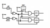
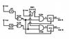
- which of the switches are the sensors, which are the controls?
- What are the inputs to the flipflops (clock, set, reset, ...)?
- What are the outputs of the flipflops supposed to indicate or control?
A short description of how the tailgate control is supposed to work will help incredibly in analysing your 'circuit'.
Why use inverters after S1 and S2? tie the switches to GND instead and remove the inverters.
Add pull-Up or Pull-down Resistors (depending on the logic) to the gates that have switches at their inputs to avoid floating inputs.