Maker Pro
Maker Pro

Food mixer power supply dead.

Lake_M

Dec 17, 2017
5
Joined
Dec 17, 2017
Messages
5
Hi guys,

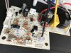
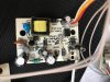
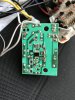
I've been trying to diagnose my wife's dead food mixer without much success. The problem is probably the power supply as I don't get any LED's or sign of any life whatsoever. The mixer is only 18 months old but out of warranty. There are two PCB's; the larger one contains mains input and the TRIAC that goes to the motor. On the same board there is a low voltage side which I assume provides the TRIAC regulation. There is a separate small PCB which houses a switching transformer circuit. The filtered mains goes via two cables to this small board, then returns to the main board via three low voltage cables after AC rectification and small switching transformer. When powered up, I'm only getting 0.3v between the low voltage connections on the small board. I've had most of the components out and tested them. The inductor was blown, and the Schotky diode was blown. The transformer, optocoupler and capacitors are good. The small IC on the under side (I assume) is some kind of PWM or regulation but it's not labelled. I still think the issue is with this board.
Why is there three cables returning to the main board from the small board and not two? What voltage would it likely be producing? The transformer has a label 13 - 2.5 mH. I might be able to buy a replacement board if I knew what this board was putting out.

I've attached some photos of the boards.

Any help appreciated. - thanks in advance.
Andy.
 

Attachments

  • IMG_0199.JPG
    IMG_0199.JPG
    347.8 KB · Views: 96
  • IMG_0200.JPG
    IMG_0200.JPG
    82 KB · Views: 118
  • IMG_0202.JPG
    IMG_0202.JPG
    379.6 KB · Views: 101

73's de Edd

Aug 21, 2015
3,629
Joined
Aug 21, 2015
Messages
3,629
Sir Lake_M . . . . .

The inductor was blown, and the Schotky diode was blown.

From the boards construction / design I would take the use of a " Scottish " ( well . .Hell . .that's what Spel-chek, sez it shud be ? ) diode as being the D8 diode at the very top of the board, and being within the "cold" / isolated secondary of the power supply.
( UNLESS you erred in expecting that units fwd voltage to be on up into the 6-700 mv range ? vice its MUCH lower 100-200mv value)
Coming down the board a bit and then reading all across, you have the blue varistor snubber -the power transformer and the 4 lead optical isolator at far right.
All circuitry below that point is AC line "HOT"
Q001 is your power oscillator and D006 its damping diode.
And you say that the bottom of the board L001 filter inductor, coupling between a the two ~200 VDC main filter caps was open.
Guessing its colors are . . .
1st band . . .BROWN ?-RED?
2nd band . . VIOLET?
3rd band . . BLACK ?
4th band . . Silver?
D001 thru D004 seem to all be 1N4007's as the units FWB configured rectifier, with D005 and D007 also probably being '007's..
Does DVM testing in diode test mode still reveal good junctions on all of those diodes ?
Also can you confirm good junctions on Q001 ?

Looks like this unit could possibly be as old as 6 yrs.
Is the black shrink wrapped unit (fuse) at the right corner of the board in the COLD AC return lines WHIT wire, being the original and that part never has blown ? Is it assigned F001 ?
Talk to me . . . .

73's de Edd


.
 

Lake_M

Dec 17, 2017
5
Joined
Dec 17, 2017
Messages
5
Sir Lake_M . . . . .

The inductor was blown, and the Schotky diode was blown.

From the boards construction / design I would take the use of a " Scottish " ( well . .Hell . .that's what Spel-chek, sez it shud be ? ) diode as being the D8 diode at the very top of the board, and being within the "cold" / isolated secondary of the power supply.
( UNLESS you erred in expecting that units fwd voltage to be on up into the 6-700 mv range ? vice its MUCH lower 100-200mv value)
Coming down the board a bit and then reading all across, you have the blue varistor snubber -the power transformer and the 4 lead optical isolator at far right.
All circuitry below that point is AC line "HOT"
Q001 is your power oscillator and D006 its damping diode.
And you say that the bottom of the board L001 filter inductor, coupling between a the two ~200 VDC main filter caps was open.
Guessing its colors are . . .
1st band . . .BROWN ?-RED?
2nd band . . VIOLET?
3rd band . . BLACK ?
4th band . . Silver?
D001 thru D004 seem to all be 1N4007's as the units FWB configured rectifier, with D005 and D007 also probably being '007's..
Does DVM testing in diode test mode still reveal good junctions on all of those diodes ?
Also can you confirm good junctions on Q001 ?

Looks like this unit could possibly be as old as 6 yrs.
Is the black shrink wrapped unit (fuse) at the right corner of the board in the COLD AC return lines WHIT wire, being the original and that part never has blown ? Is it assigned F001 ?
Talk to me . . . .

73's de Edd


.

Thanks for the reply Edd.

Yes D008 was the "Scottish" diode I replaced - it was shorted.

The inductor colours are:- Red, Purple (Violet), Brown, Silver. It wasn't just open, it was blown open!

Yes, F001 is the fuse you referred to and it's good.

Q001 transistor tested out of circuit and all good.

Yes the WHITE wire is NEUTRAL (return), and the BLACK is LIVE (Hot).

I took diodes D006 and D007 out and tested them - all good.

I tested D001, 002, 003, 004, and 005 in circuit and I got 600mv (ish) so assumed good.

The transformer has two separate windings on the first core (primary and auxiliary?) - 4 pins, and one winding on the secondary - 2 pins.

Still not sure why there are three leads coming from the board if there is only one secondary winding on the transformer .... +ve / -ve and ground?

I would like to use my bench PSU to inject a small DC voltage into the return pins on the main board to see if I can bring that board to life - but three pins??

Thanks again,

Andy
 

73's de Edd

Aug 21, 2015
3,629
Joined
Aug 21, 2015
Messages
3,629
Sir Lake_M . . . . .

We can work with both side pics of the power supply . . . . as you provided.

Seems like the CON1 and its wiring between the boards is having . . . .
  • A common DC ground as the central WHITE wire and
  • A DC voltage supply carried to the other board via the YELLOW wire, and
  • The final RED wire is inter sampling between the two boards via the optical isolator. on the power supply board.
The R004 grey film resistor blocks my viewing the board designation of the O.I.. Can you provide both it and the part number of the O.I. . . . with it likely akin to being a common PC817 ?
What is the DC voltage and cap value of C009 . . .in order to guesstimate the max operating voltage for the second boards DC supply?.

Also it wouldn't hurt to have the voltages and cap ratings of the pair that bracket either side of the L001 inductor, as well as the smaller C004 ? that sits besides them.

Also the Q001 transistor, and the new kid on the block . . . as being that 8 pin U001 on the bottom . . . it being the brains of the SMPS.

That C004 is probably working with a dropping resistor and a zener to provide its U001's power supply .

Can you re-shoot the controller board component side head on . . . . .as its currently too sloped and askew. . . .to be able to recreate a placed side by side board comparison.

Also shoot the foil side as I see a 6 MHZ xtal for the IC on the foils side of the board, as you didn't initially provide that pic also..

73's de Edd
 

Lake_M

Dec 17, 2017
5
Joined
Dec 17, 2017
Messages
5
Thanks for the reply Edd,

The OI is a 817C as you correctly identified. (L1046 817C W)

I can't see a C009 cap on the power board, but the C006 cap sitting right at the output is 100uF at 25v.

The two caps straddling the inductor (C001 and C002) are both 4.7uF at 400v.

The Q001 transistor is (I think based on the markings I can read) a APT 13003E NPN power transistor.

There are no markings on the 8 pin IC U001 unfortunately.

I've re shot the controller board as requested.

What would be the DC voltage out of the bridge rectifier if the input was 240V?
These are 1N4007 D9 diodes. I was measuring 120V is this right?IMG_0205.JPG IMG_0204.JPG

Thanks again.

Andy.
 

Alec_t

Jul 7, 2015
3,591
Joined
Jul 7, 2015
Messages
3,591
I'd check if there are unintentional solder bridges at the three highlighted points in the pic below :
Bridges.jpg
 
Last edited:

Lake_M

Dec 17, 2017
5
Joined
Dec 17, 2017
Messages
5
Just as a quick update.... whilst I still intend to get to the bottom of the OEM controller board fault, I built and installed an AC controller kit from Velleman (K2636) and it works OK.
The motor is a 1000W universal brushed motor which works with both AC and DC. I noticed with the K2636 AC controller that the brushes spark quite a lot, but when the motor is driven directly from my bench DC supply the brushes don’t spark at all. I’m wondering if it would be possible (or sensible!) to insert a suitably rated bridge rectifier on the output of the AC speed controller with the hope that it would stop the sparking. BTW the commutator is clean but it seems to make no difference, nor does the speed at which the motor is being driven.
 

Lake_M

Dec 17, 2017
5
Joined
Dec 17, 2017
Messages
5
Lake_M, I recently also fixed a seemingly dead food processor displaying similar symptoms. In my case it appeared to be just a blown Zener diode causing the problem.

Obviously not all food processors are the same, though maybe something in the thread where Dorke helped me repair it might help in your case?

https://www.electronicspoint.com/threads/farberware-food-processor-fp3000fbs.286082/


Hi and thanks for the link. Glad you sorted the problem out with the help of the forum. These guys really know their stuff. I *will* find the fault on the control board. It's become a bit of a "it's that thing or me!" kind of challenge (much to the annoyance of my wife who thinks I've wasted too long on it already).
 

Chas

Oct 26, 2017
50
Joined
Oct 26, 2017
Messages
50
Hi and thanks for the link. Glad you sorted the problem out with the help of the forum. These guys really know their stuff. I *will* find the fault on the control board. It's become a bit of a "it's that thing or me!" kind of challenge (much to the annoyance of my wife who thinks I've wasted too long on it already).

I was in exactly the same boat! The amount of hours I spent fault finding and repairing made no logical sense. However, I looked at it as a hobby, and it's better to be doing something actively rather than just being a couch potato and sitting in front of the TV. A far more constructive use of my free time, even though my other half likens me me to a tenacious Jack Russell with an old rag - "you just won't give up will you?" I got told!

Hope you get yours sorted too, and yes, the knowledge from the guys on this forum is amazing. I hope that one day I will have even a fraction of what they know.
 
Top