Maker Pro
Maker Pro

High Frequency Preamp

Raven Luni

Oct 15, 2011
798
Joined
Oct 15, 2011
Messages
798
Greetings,

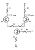
It will be bat season soon and I'm messing about with amplifier designs again :p
This time I'm looking to miniaturise everything and use surface mount components. Does this preamp look ok? The input is from an electret and the purpose is basically to amplify the **** out of high frequencies to drive a logic counter (so aiming for saturation).

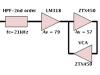
Questions: I imagine another voltage stage will probably be in order - if so should that go before or after the HP filter and also does loading affect the filter performance or would a buffer be needed?

hppreamp.gif
 

Raven Luni

Oct 15, 2011
798
Joined
Oct 15, 2011
Messages
798
Additional thoughts: Should the zener be in series with the 1k resistor?
Also with regard to the HP filter: would it be rendered useless if clipping occured before filtering (since clipping is basically adding a near infinite number of odd harmonics)
 

(*steve*)

¡sǝpodᴉʇuɐ ǝɥʇ ɹɐǝɥd
Moderator
Jan 21, 2010
25,510
Joined
Jan 21, 2010
Messages
25,510
As the circuit is drawn, turning on the second transistor (always worth labelling your components) to the point at which the zener conducts will allow a potentially large current to flow for no good effect.

I would recommend a resistor between the emitter of the transistor and the zener (1K should be fine).

Another option is to have some form of ACG on your circuit where the gain is determined by the average (over time) of the output of your amplifier.
 

DuctDuck

Jan 26, 2013
52
Joined
Jan 26, 2013
Messages
52
You could use a bjt differential amp with vca (voltage control amplification) made using 3 bjts.
I suggest this only because your amplitude control affects Av of Q1 (first stage; I like your bias arrangement for a filter...no Remmitter?) and hampers the double filter output of Q2 (not practical; unique, but not practical).

Additionally, my preliminary calculations for Q1...
ICQ=0.656 mA
RIN=3.745kOhm
fc=425Hz

Yes, fc is very low for bat signals, err uhm, bat singing/voices? I would like to know more of what you know and reasons for pursuing bats, please.

ps-the zener has to go, if you want to clip signals then shrink Vce
 

Attachments

  • audio-diff-amp-cv.png
    audio-diff-amp-cv.png
    12.6 KB · Views: 143
Last edited:

Raven Luni

Oct 15, 2011
798
Joined
Oct 15, 2011
Messages
798
Steve: Looked at some AGC stuff and couldnt make sense of it :p

Duck: The local wildlife place does bat walks every year and making detectors is a really fun project. You can find my older attempts in the projects section. Also, as for the frequency - I used the formula sqrt(2) / (4 * Pi * R1 * C2) - where R1 is the 100R + the 10K variable and C2 is the 1nF
 

DuctDuck

Jan 26, 2013
52
Joined
Jan 26, 2013
Messages
52
Hmmm, very cool! I like the lastest bat detector. Not only does it detect bats' chirps by an electret microphone but it produces an audible analog of the chirp. It's not a long bird song sound? It's a little chirp?

Getting back to your new design goal, typically filtering is done before voltage amplification using the original signal (mind you, a bandpass filter can eliminate higher frequencies being picked up too; i.e- highpass followed by lowpass). Yet carefully consider Re-Rb reflection and loading of a filter (fc=1/(2piRC)).
Often, simulators don't have re (ie-Re prime, or h-ie) as a defined parameter or give an incorrect weight reducing its actual impact.

ps-yup, you're right to use a single bjt to amplify signal to ****, if you want a reduced circuit size; sorry.
 
Last edited:

(*steve*)

¡sǝpodᴉʇuɐ ǝɥʇ ɹɐǝɥd
Moderator
Jan 21, 2010
25,510
Joined
Jan 21, 2010
Messages
25,510
Steve: Looked at some AGC stuff and couldnt make sense of it :p

AGC can be thought of as a combination of 2 devices.

The first device is a voltage controlled amplifier. This is one where the gain of the amplifier is determined by a voltage somewhere.

The second component is something to convert the "loudness" of the output over a period of time to a voltage. A simple approach to this is to rectify and filter the audio signal with some load to cause the charge on the capacitor to leak away.

The magic is in combining these so that the voltage determined by the "loudness" of the voltage controlled amplifier is fed back to the voltage input of the voltage controlled amplifier in such a way that the gain is reduced when the output signal gets louder.

When applied to audio, this can also be called "compression"

If used with a microphone, the effect is that when ambient sound levels are low, the amplifier is working at a high gain, but as the sound level increases, the gain reduces.

I think that's what you're after, so that a bat way over there ----> can still be heard, whilst a bat flying over your head doesn't blast out your ears.
 

(*steve*)

¡sǝpodᴉʇuɐ ǝɥʇ ɹɐǝɥd
Moderator
Jan 21, 2010
25,510
Joined
Jan 21, 2010
Messages
25,510
Here is a circuit that might help.

I've not analysed it. Node that the output voltage is quite low and relatively constant for a very large range of input voltages.

For your use (if I am correct above), you would probably want to have an active high pass filter, then this circuit, then an amplifier.

On the same page you'll find a link to this. This is an example of what I mentioned above (the jfet controls the gain of the amplifier and the voltage across the capacitor C1 is dependant on the average output voltage of the op-amp). However I'm not entirely happy about the design of this T2 is wrong for so many reasons...

Note that R2 is not across T1! T1 and R1 form an attenuator (volume control) that is adjusted by the voltage at the gate of T1. The 741 is set up with a fixed gain.
 

DuctDuck

Jan 26, 2013
52
Joined
Jan 26, 2013
Messages
52
I hope you don't mind terribly, Raven, but I have been developing some figures for your bat detector using a reasonably good electret (e.g.- 96 dB working range, -44dB sensitivity, and S/N of 60dB).

If a bat is flying 10 meters ahead (e.g.- height of a tree, belfry, etc), and mic has a breadth of 1 meter (i.e- arm sweeps meter in an arc). An emitted chirp, directly in front, locates a substantial moth (blech); then there could be 40 nW of a sound in this path at the mic.

I might be missing something. If you have a scenario and could take me through it I may be able to arrive with some figures.
 
Last edited:

DuctDuck

Jan 26, 2013
52
Joined
Jan 26, 2013
Messages
52
Oopsy, :eek: I have to correct this...again. (96dB-60dB) is the dynamic range of the electret.

60dB is the lowest signal level; signals must be louder than this noise level. It's intensity is 10(uW/sq.m).
96dB is the maximum signal level of the electret. It's intensity is 3.98(mW/sq.m).

A bat flying 10m ahead and chirps; a 120dB signal. A mic would encounter a 10(mW/sq.m) signal. And if the chirp was 96dB, a mic would encounter 39.8(uW/sq.m)!

These figures account for the 10m distance using inverse square relation of intensity to distance. That's it!


Sorry, Raven Luni, for not being totally clear and confident, I haven't given audio transducers a minute of time! I would have to start here with audio levels before moving to an amplifier's design.
 
Last edited:

DuctDuck

Jan 26, 2013
52
Joined
Jan 26, 2013
Messages
52
This may not be as valuable to you, Raven Luni, as it is to me. Yet I can exclaim "ahha!" My understanding of sound transducers is improved. I have a roughly hatched bat detector plan for myself and you.

I encountered numerous instances of the deciBell scale while researching electrets, sound levels and bats, which ordinarily isn't a problem within electronics. But converting from a power dB to a voltage dB involves sharing the impedance parameter. I couldn't see shared parameters for converting sound intensity dB (i.e.-sound source) to sound pressure dB (i.e.-pressure at electret). This will be worth investigating during prototyping and redesign phase.

So far, the input signal must be higher than 100dB; based on sound intensity's fading over a distance and mic's S/N rating (e.g.- 40dB loss for 10m distance, 60 dB S/N). As most bat chirps are measured at 10cm and normal intensity measures use 1m, a -20dB deduction corrects for this (e.g.- -6dB per doubling of distance; an octave, so -6dB at 20cm again at 40cm again at 80cm,etc) and will be applied for intensity to pressure conversion later. So, -40dB at 10m it is. Of course some electrets have a different S/N rating too. Supposedly the frequency range is nearly constant for these devices and extended range behavior continues this trend yet is more reliable for smaller devices than 6mm diameter devices or larger: gee! A flat response is desirable yet isn't documented in the data sheets.:rolleyes:

The Agc/Vca stage requires 1Vpk minimum for signal voltage; Vbe barrier, so why not have a 2Vp-p output signal fed to a negative clamp using signal diodes, and this dc voltage controls the transistors' emitter current? The bjt amplifier will have a varying gain from (1 - 57). A simple, linear signal compressor.

Unfortunately I only have some Zetex to-92 bjts (ztx450 npn, ztx550 pnp). While they aren't a match to your prefered fmmt493 smt device; substitution will be a minor issue as current levels are very low (e.g.-10mA) and--the persistant knit to pick-- Miller effect capacitance will be swamped out by low resistance levels.

Are you developing plans along these lines or another direction, Raven Luni?
 

Attachments

  • bat-detector-01.png
    bat-detector-01.png
    7.5 KB · Views: 100

DuctDuck

Jan 26, 2013
52
Joined
Jan 26, 2013
Messages
52
Uhh, yeah. I guess there is no chance of you crunching my sound pressure levels, Kirs? Right...

Or, you can go back and look at my process diagram, you might see a big mistake...

After the filter (connected to the first amp, Av=79), the amplifier should have an overall (voltage) gain of 4500! How do you suppose that is going to happen?

3xbjt stages, each with Av=166 but uses feedback impedance for Av=16.6. And this Vout will be at 1Vpk minimum. And there is a parallel VCA stage controlling another low gain bjt amplifier.

How many bjts was that again?
 
Top