Sir gerryt . . . . . . (and that's being very heav-
E E E E E E E E on the
Teeeeeeeeeeeeeeeeeeee !)
How 'bouts us doing some super dooper uber- techno sniffing, using but a mere length of hook up wire and a 47 or 100'ish ufd @16(+) E-cap.
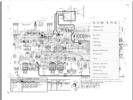
I have re-diddled-ed-ed your units schema of the sole area of interest and put a bit more of vertical spacing between its
CHANNEL 1 and
CHANNEL 2 sections.
LE REFERENCE . . . . . 'cest petite
View attachment 59859
FIRST STEP . . . .
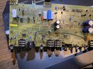
Fire up the unit and get it making the CHANNEL 1's quite noticeable HUMMMMMM . . .chum.
Now, for just backing up your prior testing of grounding integrity.
Take said hook up wire . . . of such length to be able to span from
GREEN SQUARE U1 Pin 5 to both U2 Pin5 and JB connector pin 1.
With our experiencing no fault with intregrity of
GREEN SQUARE U1 Pin 5 and its connecting to its . . . SG . . .
Signal Ground.
Lets confirm no excess rosin or conformal coating . . . to let us make a good connection to one bared end of hook up wire and span its other end up to connect to same the like condition of U2 pin 5 and its Signal Ground.
If no change in Hummmmmmmm lift up that just made connection and transfer up to JB2 pin 1.
If the hummmmmmm remains, our required grounds are O.K.
NEXT STEP . . . . .
Take the E-cap to be used and . . .likely it will be a radial unit . . . . and grip . . . . probably its insulated case . . . .between index finger and thumb and see if the touching of either one leads of the E-cap to pin 3 or 3 of the JB2 connector will over ride your hum, so as to be heard. If not use your other hand to tightly grasp around the insulated amps AC cord .
Thus your increased AC level injection into the amp . . . .a la body coupling.
Once you attain a noticeable level to make judgement with, test both caps leads to JB #2 or 3 to see if one lead is producing stronger hum.
If so, note that lead, as it needs to be solder tacked to that wire end and the other wire end stays at . . . and is solder tacked to U2 pin 5 the
Sig Gnd or at U2 pin 5
Sig Gnd . . . . . take your pick.
Should you not be able to differentiate, just have the cap - going / soldering to the wire.
OBSERVATIONS . . . .
Note that
Channel 1 and
2 outputs both meet at the
RED and
BLUE STARS to join at the small
GREEN square to be co amplified by
LARGE GREEN SQUARE U1.
Here you have no problem with
CHANNEL 2 . . . . .at the
BLUE STAR . . . .
BUT . . . . the
CHANNEL 1 RED STAR line is carrying in
Hummmmm with it back from U2.
We are now going to take the E-cap and its extension ground wire and start at the
U2 pin 7 and touch that free cap lead to it and expect an initial pop and then connect just long enough to see if the HUMMMM remains.
Lift E-cap and ground it to its other wire end to DC discharge it. ( Also, every test time . . .hereafter )
Touch E-cap lead to U2 #6 and check for presence or loss of that HUMMMMM.
THEN YOU SAY. . . .
As the volume in channel 1 is increased there is a hum that gets louder. It does not sound like a 60 cycle hum.
With a linear power supply and FWB . . . . 120~ hummmmmmm . . . . . . but lets just call it HUMMMMM for now
Now we're getting down to the U2 pin 6 and testing it . . . . noting results.
Then move to U2 pin 1 and testing it . . . . noting results.
Finally U2 pin 2 and then pin 3.
If you still had Hummmmmmmmmm at the last pins 2 and 3, I am wanting to suspect it being introduced from the SHARED power supply to U2.
The channel 2 has quite high input levels and would be MORE tolerant of power supply ripple.
NOW if you look at the
CHANNEL 1 and the meager 2 and 10 mv input levels and the degree of required amplification, power supply ripple would be more significant in that CHANNEL 1 in its U2 supply.
REFERENCING . . .
The
YELLOW SQUARE inset gives their shared power supply and the MC33078 snippet gives its power pin outs.
Don't be afraid to go on ahead and tack two good 470 ufds across the existing ones . . . . correct polarity observed . . . (vewy-vewy cawefuwwy! ) to test for
Hummm elimination . . . . thus confirming it was timely decline of those caps..
Feed back the conditions at all of the tested U2 AF inputs and outputs . . . . . . . I be . . .
Thaaaaaasssssit . . . . .
73's de Edd . . . . .
When I was a little boy, I was told that I had a disease that required me to eat dirt three times a day in order to survive...
It's certainly a good thing that my big brother told me about it !
.