Maker Pro
Maker Pro

Led Audio (Mic) VU meter

Lizard

Sep 16, 2014
3
Joined
Sep 16, 2014
Messages
3
Hi.
I'm trying to make quite a big LED audio Vu meter.

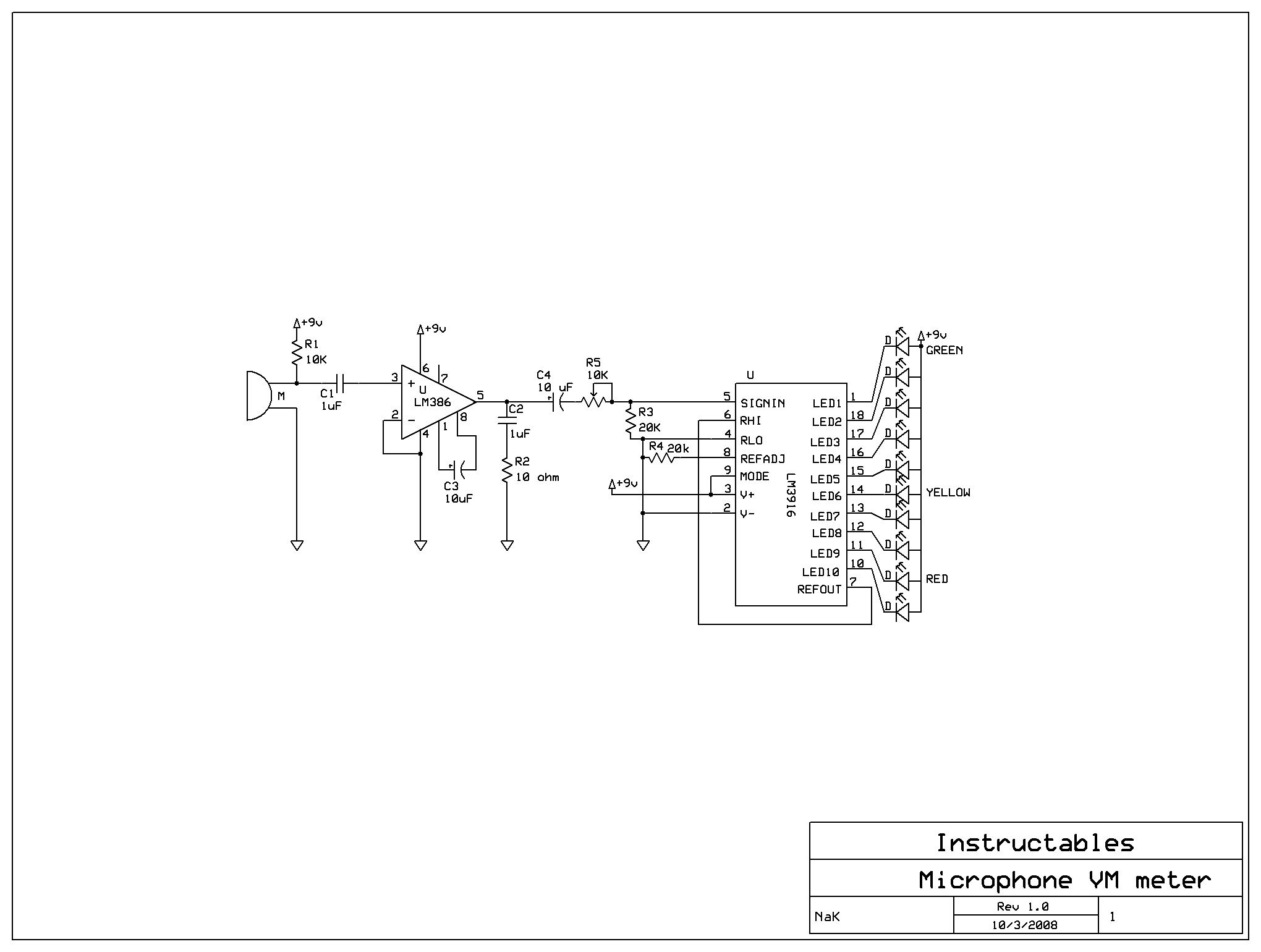
I've found this schematic:
FX567GSFLROK12R.gif


1)
But my power source is 7.4V and not the 9V it uses.
I'm pretty sure I'd have to change R1, is there more to be changed.

2)
If I wanted more LEDs, let's say 40 instead of 10, could one LM3916 handle this amount somehow?
I've read that the LM3916 has an output limit, will it blow If connect these LEDs in series+parallell (max 20mA each, ±2V forward Voltage)
 

(*steve*)

¡sǝpodᴉʇuɐ ǝɥʇ ɹɐǝɥd
Moderator
Jan 21, 2010
25,510
Joined
Jan 21, 2010
Messages
25,510
I would advise you to look up the datasheet for this chip. They show how to cascade multiple chips and describe the calculation of resistor values etc.
 

KrisBlueNZ

Sadly passed away in 2015
Nov 28, 2011
8,393
Joined
Nov 28, 2011
Messages
8,393
That's a pretty poor design. There are so many problems with it that I don't want to start describing them all because I would be here all day. But the LM3916 is the right IC to use. The data sheet is at http://www.ti.com/lit/ds/symlink/lm3916.pdf. I STRONGLY recommend you use a different design that still uses the LM3916. Do some Googling or use one of the designs in the data sheet.

The value of the resistor that feeds supply current into the microphone (R1 in that design) is not critical. Do you have any information on the microphone you will be using?

When you say you want to drive 40 LEDs instead of just ten, do you mean that you want ten "segments" but you want four LEDs in each? Or do you mean you want to expand the number of segments from ten to 40? The latter might be tricky because of the logarithmic response of the LM3916. The former is possible but will require extra components.

Driving multiple LEDs from a single output with a 7.4V supply can be done by paralleling LEDs (preferably with individual current limiting resistors) but as you said, this increases the load on the device and could damage it. The proper way is to use a transistor or MOSFET as a buffer on each output - for example, a PNP transistor (e.g. a 2N3906) with its emitter connected to the positive supply rail.

When the LM3916 wants to illuminate an LED, it pulls its output pin low. This pin can be connected directly to the base of a buffer transistor, because the LM3916 has current-limited outputs. This turns the buffer transistor ON and it pulls its collector up to the positive supply rail. The collector can drive four LEDs, either in parallel with individual current limiting resistors, or in two series chains.

270327.001.GIF
See https://www.electronicspoint.com/resources/got-a-question-about-driving-leds.5/ for guidance on how to choose the series resistor values.

Set the LM3916's LED current to around 1.5 mA by setting the resistance between pin 7 and 0V as described in the data sheet. This will provide about 1 mA of base current to each transistor. The actual LED currents will be determined by the series resistors, as described in that resource on Electronics Point.
 

Lizard

Sep 16, 2014
3
Joined
Sep 16, 2014
Messages
3
I want to use 4 LEDs per segment to clear that up. I am not planning on cascading the LM3915. Just like KrisBlueNZ suggested.

The mic I am trying to use is an electret microphone with no obvious markings as far as I can see:
eszitoI.jpg
On page 14 of the LM3916 Datasheet there is more information on Audio Vu meters, I know (assume) that I do need to amplify the electret mic as its output is very small.
I presume the LM386 is the wrong IC for this job.

I have also checked the Datasheet for the 2N3906, it allows 200mA, that should allow putting in 10 (instead of the 4 on your example circuit) LEDs with ease.

On an unrelated note: How do you make those circuit pictures?
 

(*steve*)

¡sǝpodᴉʇuɐ ǝɥʇ ɹɐǝɥd
Moderator
Jan 21, 2010
25,510
Joined
Jan 21, 2010
Messages
25,510
On page 14 of the LM3916 Datasheet there is more information on Audio Vu meters, I know (assume) that I do need to amplify the electret mic as its output is very small.

Yes, correct.

I presume the LM386 is the wrong IC for this job.

It wouldn't be my first choice.

A question for you: Is the microphone to be used only for the VU meter, or do you intend to use the signal for something else (recording it, for example)? If the former, then you don't need to care about distortion or even moderate amounts of noise. If the latter then you want a properly designed preamp.

I have also checked the Datasheet for the 2N3906, it allows 200mA, that should allow putting in 10 (instead of the 4 on your example circuit) LEDs with ease.

You'd think that, but it is normal to not take the transistor right to it's limits. In any case, you may hit other limits before you hit the 200mA current. However, using Kris' circuit 200mA would suffice for 20 LEDs at 20mA each, so driving 10 would only require a current of 100mA, and that would be reasonable for this transistor.

Another thing you would want to consider is whether you use line or dot mode of the LM3916. If you're using line mode and you have 12 segments alight, and each segment takes 200mA, that's a total required current of 2.4A from your power supply. You;ll find that the datasheet warns about package dissipation for the LM3916 when used in bar mode with high LED currents. Whilst this doesn't apply when you use switching transistors as per Kris' circuit, it still means that the entire circuit is consuming a *lot* of power.

On an unrelated note: How do you make those circuit pictures?

I'll let Kris answer that. Each of the moderators has their own favorite tool. I tend to use the free on-line tool provided by digikey because I'm often out and about while answering posts.
 
Last edited:

Lizard

Sep 16, 2014
3
Joined
Sep 16, 2014
Messages
3
A question for you: Is the microphone to be used only for the VU meter, or do you intend to use the signal for something else (recording it, for example)? If the former, then you don't need to care about distortion or even moderate amounts of noise. If the latter then you want a properly designed preamp.

It would be only for the VU meter.

I'll definitely be going with the transistors.
The battery it would be running of is rated for 100A continuous discharge, so this should definitely be enough.
Running in bar mode, a 5000mAh battery should be able to power the circuit for at least an hour or two.
(I have 2 of these batteries, I can look into hooking them up in parallel if need be.)
Data:
10 segments
10 LEDs/segment in series of 2

That would be 100mA / segment with one LED at 20mA
That would give 1A for the 10 segments

This gives a theoretical time of 5 hours.
I left out the LM3915, resistors, transistors ( LEDs will be power hungry, the rest is negligible?)


I'll let Kris answer that. Each of the moderators has their own favorite tool. I tend to use the free on-line tool provided by digikey because I'm often out and about while answering posts.
The Digikey tool has quite a nice interface. It's not overly complicated like the most tools I tried (and free), thanks for that.
 

(*steve*)

¡sǝpodᴉʇuɐ ǝɥʇ ɹɐǝɥd
Moderator
Jan 21, 2010
25,510
Joined
Jan 21, 2010
Messages
25,510
It would be only for the VU meter.

In that case, if the 386 provides enough gain, go with it. It has the advantage of being simple. It is however an amplifier rather than an op-amp, and only has a max gain of 200.

For this application you might be looking at a precision rectifier followed by an RC circuit to "average" the output voltage. This may require a negative supply rail and an op-amp. I'm sure if you google "LM3916 VU meter" you'll get some hits.

This is a really old circuit, but it might do the trick. You may have to wind up the gain a bit to use a mic directly.

edit: For an instructable, that's not the worst circuit I've seen. Electret mics probably have fairly similar output levels, so (not having made it or done any calculations) I'd go with the practical experience of whoever made it in this case. If it's not sensitive enough you may have to look at a better front end.
 
Last edited:
Top